Drag coefficient

Last updated
Drag coefficients in fluids with Reynolds number approximately 10 Shapes are depicted with the same projected frontal area 14ilf1l.svg
Drag coefficients in fluids with Reynolds number approximately 10 Shapes are depicted with the same projected frontal area

In fluid dynamics, the drag coefficient (commonly denoted as: , or ) is a dimensionless quantity that is used to quantify the drag or resistance of an object in a fluid environment, such as air or water. It is used in the drag equation in which a lower drag coefficient indicates the object will have less aerodynamic or hydrodynamic drag. The drag coefficient is always associated with a particular surface area. [3]

Contents

The drag coefficient of any object comprises the effects of the two basic contributors to fluid dynamic drag: skin friction and form drag. The drag coefficient of a lifting airfoil or hydrofoil also includes the effects of lift-induced drag. [4] [5] The drag coefficient of a complete structure such as an aircraft also includes the effects of interference drag. [6] [7]

Definition

Table of drag coefficients in increasing order, of 2D shapes between walls (right column) and 3D shapes (left column), depicted with the same projected frontal area, at Reynolds numbers between 10 and 10 with flow from the left Hoerner fluid dynamic drag coefficients.svg
Table of drag coefficients in increasing order, of 2D shapes between walls (right column) and 3D shapes (left column), depicted with the same projected frontal area, at Reynolds numbers between 10 and 10 with flow from the left

The drag coefficient is defined as

where:

The reference area depends on what type of drag coefficient is being measured. For automobiles and many other objects, the reference area is the projected frontal area of the vehicle. This may not necessarily be the cross-sectional area of the vehicle, depending on where the cross-section is taken. For example, for a sphere (note this is not the surface area = ).

For airfoils, the reference area is the nominal wing area. Since this tends to be large compared to the frontal area, the resulting drag coefficients tend to be low, much lower than for a car with the same drag, frontal area, and speed.

Airships and some bodies of revolution use the volumetric drag coefficient, in which the reference area is the square of the cube root of the airship volume (volume to the two-thirds power). Submerged streamlined bodies use the wetted surface area.

Two objects having the same reference area moving at the same speed through a fluid will experience a drag force proportional to their respective drag coefficients. Coefficients for unstreamlined objects can be 1 or more, for streamlined objects much less.

As a caution, note that although the above is the conventional definition for the drag coefficient, there are other definitions that one may encounter in the literature. The reason for this is that the conventional definition makes the most sense when one is in the Newton regime, such as what happens at high Reynolds number, where it makes sense to scale the drag to the momentum flux into the frontal area of the object. But, there are other flow regimes. In particular at very low Reynolds number, it is more natural to write the drag force as being proportional to a drag coefficient multiplied by the speed of the object (rather than the square of the speed of the object). An example of such a regime is the study of the mobility of aerosol particulates, such as smoke particles. This leads to a different formal definition of the "drag coefficient," of course.

Cauchy momentum equation

In the non dimensional form of the Cauchy momentum equation, the skin drag coefficient or skin friction coefficient is referred to the transversal area (the area normal to the drag force, so the coefficient is locally defined as:

where:

Background

Flow around a plate, showing stagnation. The force in the upper configuration is equal to

F
=
1
2
r
u
2
A
{\displaystyle F={\frac {1}{2}}\rho u^{2}A}

and in the lower configuration

F
d
=
1
2
r
u
2
c
d
A
{\displaystyle F_{d}={\tfrac {1}{2}}\rho u^{2}c_{d}A} Cd flat plate.svg
Flow around a plate, showing stagnation. The force in the upper configuration is equal to

and in the lower configuration

The drag equation

is essentially a statement that the drag force on any object is proportional to the density of the fluid and proportional to the square of the relative flow speed between the object and the fluid. The factor of comes from the dynamic pressure of the fluid, which is equal to the kinetic energy density.

The value of is not a constant but varies as a function of flow speed, flow direction, object position, object size, fluid density and fluid viscosity. Speed, kinematic viscosity and a characteristic length scale of the object are incorporated into a dimensionless quantity called the Reynolds number . is thus a function of . In a compressible flow, the speed of sound is relevant, and is also a function of Mach number .

For certain body shapes, the drag coefficient only depends on the Reynolds number , Mach number and the direction of the flow. For low Mach number , the drag coefficient is independent of Mach number. Also, the variation with Reynolds number within a practical range of interest is usually small, while for cars at highway speed and aircraft at cruising speed, the incoming flow direction is also more-or-less the same. Therefore, the drag coefficient can often be treated as a constant. [13]

For a streamlined body to achieve a low drag coefficient, the boundary layer around the body must remain attached to the surface of the body for as long as possible, causing the wake to be narrow. A high form drag results in a broad wake. The boundary layer will transition from laminar to turbulent if Reynolds number of the flow around the body is sufficiently great. Larger velocities, larger objects, and lower viscosities contribute to larger Reynolds numbers. [14]

Drag coefficient Cd for a sphere as a function of Reynolds number Re, as obtained from laboratory experiments. The dark line is for a sphere with a smooth surface, while the lighter line is for the case of a rough surface. The numbers along the line indicate several flow regimes and associated changes in the drag coefficient:
*2: attached flow (Stokes flow) and steady separated flow,
*3: separated unsteady flow, having a laminar flow boundary layer upstream of the separation, and producing a vortex street,
*4: separated unsteady flow with a laminar boundary layer at the upstream side, before flow separation, with downstream of the sphere a chaotic turbulent wake,
*5: post-critical separated flow, with a turbulent boundary layer. Drag coefficient on a sphere vs. Reynolds number - main trends.svg
Drag coefficient Cd for a sphere as a function of Reynolds number Re, as obtained from laboratory experiments. The dark line is for a sphere with a smooth surface, while the lighter line is for the case of a rough surface. The numbers along the line indicate several flow regimes and associated changes in the drag coefficient:
•2: attached flow (Stokes flow) and steady separated flow,
•3: separated unsteady flow, having a laminar flow boundary layer upstream of the separation, and producing a vortex street,
•4: separated unsteady flow with a laminar boundary layer at the upstream side, before flow separation, with downstream of the sphere a chaotic turbulent wake,
•5: post-critical separated flow, with a turbulent boundary layer.

For other objects, such as small particles, one can no longer consider that the drag coefficient is constant, but certainly is a function of Reynolds number. [15] [16] [17] At a low Reynolds number, the flow around the object does not transition to turbulent but remains laminar, even up to the point at which it separates from the surface of the object. At very low Reynolds numbers, without flow separation, the drag force is proportional to instead of ; for a sphere this is known as Stokes' law. The Reynolds number will be low for small objects, low velocities, and high viscosity fluids. [14]

A equal to 1 would be obtained in a case where all of the fluid approaching the object is brought to rest, building up stagnation pressure over the whole front surface. The top figure shows a flat plate with the fluid coming from the right and stopping at the plate. The graph to the left of it shows equal pressure across the surface. In a real flat plate, the fluid must turn around the sides, and full stagnation pressure is found only at the center, dropping off toward the edges as in the lower figure and graph. Only considering the front side, the of a real flat plate would be less than 1; except that there will be suction on the backside: a negative pressure (relative to ambient). The overall of a real square flat plate perpendicular to the flow is often given as 1.17.[ citation needed ] Flow patterns and therefore for some shapes can change with the Reynolds number and the roughness of the surfaces.

Drag coefficient examples

General

In general, is not an absolute constant for a given body shape. It varies with the speed of airflow (or more generally with Reynolds number ). A smooth sphere, for example, has a that varies from high values for laminar flow to 0.47 for turbulent flow. Although the drag coefficient decreases with increasing , the drag force increases.

cdItem [18]
0.001Laminar flat plate parallel to the flow ()
0.005Turbulent flat plate parallel to the flow ()
0.1Smooth sphere ()
0.47Rough sphere ()
0.81Triangular trapeze (45°)
0.9-1.7Trapeze with triangular basis (45°)
0.295Bullet (not ogive, at subsonic velocity)
1.0–1.1 Skier
1.0–1.3Wires and cables
1.0–1.3Adult human (upright position)
1.1-1.3Ski jumper [19]
1.28Flat plate perpendicular to flow (3D) [20]
1.3–1.5 Empire State Building
1.8–2.0 Eiffel Tower
1.98–2.05Long flat plate perpendicular to flow (2D)

Aircraft

As noted above, aircraft use their wing area as the reference area when computing , while automobiles (and many other objects) use projected frontal area; thus, coefficients are not directly comparable between these classes of vehicles. In the aerospace industry, the drag coefficient is sometimes expressed in drag counts where 1 drag count = 0.0001 of a . [21]

cdDrag CountAircraft type [22]
0.021210 F-4 Phantom II (subsonic)
0.022220 Learjet 24
0.024240 Boeing 787 [23]
0.0265265 Airbus A380 [24]
0.027270 Cessna 172/182
0.027270 Cessna 310
0.031310 Boeing 747
0.044440 F-4 Phantom II (supersonic)
0.048480 F-104 Starfighter

Automobile

Blunt and streamlined body flows

Concept

The force between a fluid and a body, when there is relative motion, can only be transmitted by normal pressure and tangential friction stresses. So, for the whole body, the drag part of the force, which is in-line with the approaching fluid motion, is composed of frictional drag (viscous drag) and pressure drag (form drag). The total drag and component drag forces can be related as follows:

where:

Therefore, when the drag is dominated by a frictional component, the body is called a streamlined body; whereas in the case of dominant pressure drag, the body is called a blunt or bluff body. Thus, the shape of the body and the angle of attack determine the type of drag. For example, an airfoil is considered as a body with a small angle of attack by the fluid flowing across it. This means that it has attached boundary layers, which produce much less pressure drag.

Trade-off relationship between zero-lift drag and lift induced drag Drag curves for aircraft in flight.svg
Trade-off relationship between zero-lift drag and lift induced drag

The wake produced is very small and drag is dominated by the friction component. Therefore, such a body (here an airfoil) is described as streamlined, whereas for bodies with fluid flow at high angles of attack, boundary layer separation takes place. This mainly occurs due to adverse pressure gradients at the top and rear parts of an airfoil.

Due to this, wake formation takes place, which consequently leads to eddy formation and pressure loss due to pressure drag. In such situations, the airfoil is stalled and has higher pressure drag than friction drag. In this case, the body is described as a blunt body.

A streamlined body looks like a fish (tuna), Oropesa, etc. or an airfoil with small angle of attack, whereas a blunt body looks like a brick, a cylinder or an airfoil with high angle of attack. For a given frontal area and velocity, a streamlined body will have lower resistance than a blunt body. Cylinders and spheres are taken as blunt bodies because the drag is dominated by the pressure component in the wake region at high Reynolds number.

To reduce this drag, either the flow separation could be reduced or the surface area in contact with the fluid could be reduced (to reduce friction drag). This reduction is necessary in devices like cars, bicycle, etc. to avoid vibration and noise production.

See also

Notes

  1. Baker, W.E. (1983). Explosion Hazards and Evaluation, Volume 5. Elsevier Science. ISBN   978-0-444-59988-9.
  2. AARØNÆS, ANTON STADE (2014). Dynamic response of pipe rack steel structures to explosion loads (PDF). CHALMERS UNIVERSITY OF TECHNOLOGY.
  3. McCormick, Barnes W. (1979). Aerodynamics, Aeronautics, and Flight Mechanics. New York: John Wiley & Sons, Inc. p. 24. ISBN   0-471-03032-5.
  4. Clancy, L. J. (1975). "5.18". Aerodynamics. Wiley. ISBN   978-0-470-15837-1.
  5. Abbott, Ira H., and Von Doenhoff, Albert E.: Theory of Wing Sections. Sections 1.2 and 1.3
  6. "Modern Drag Equation". Wright.nasa.gov. 2010-03-25. Archived from the original on 2011-03-02. Retrieved 2010-12-07.
  7. Clancy, L. J.: Aerodynamics. Section 11.17
  8. Hoerner, Sighard F. (1965). Fluid-Dynamic Drag : Practical Information on Aerodynamic Drag and Hydrodynamic Resistance (2 ed.). p. 3–17.
  9. See lift force and vortex induced vibration for a possible force components transverse to the flow direction
  10. Note that for the Earth's atmosphere, the air density can be found using the barometric formula. Air is 1.293 kg/m3 at 0 °C (32 °F) and 1 atmosphere.
  11. See lift force and vortex induced vibration for a possible force components transverse to the flow direction
  12. Note that for the Earth's atmosphere, the air density can be found using the barometric formula. Air is 1.293 kg/m3 at 0 °C (32 °F) and 1 atmosphere.
  13. Clancy, L. J.: Aerodynamics. Sections 4.15 and 5.4
  14. 1 2 Clancy, L. J.: Aerodynamics. Section 4.17
  15. Clift R., Grace J. R., Weber M. E.: Bubbles, drops, and particles. Academic Press NY (1978).
  16. Briens C. L.: Powder Technology. 67, 1991, 87-91.
  17. Haider A., Levenspiel O.: Powder Technology. 58, 1989, 63-70.
  18. Shapes
  19. "Drag Coefficient". Engineeringtoolbox.com. Archived from the original on 2010-12-04. Retrieved 2010-12-07.
  20. "Shape Effects on Drag". NASA. Archived from the original on 2013-02-16. Retrieved 2013-03-11.
  21. Basha, W. A. and Ghaly, W. S., "Drag Prediction in Transitional Flow over Airfoils," Journal of Aircraft, Vol. 44, 2007, p. 824–32.
  22. "Ask Us – Drag Coefficient & Lifting Line Theory". Aerospaceweb.org. 2004-07-11. Retrieved 2010-12-07.
  23. "Boeing 787 Dreamliner : Analysis". Lissys.demon.co.uk. 2006-06-21. Archived from the original on 2010-08-13. Retrieved 2010-12-07.
  24. "Airbus A380" (PDF). 2005-05-02. Archived (PDF) from the original on 2015-09-23. Retrieved 2014-10-06.

Related Research Articles

<span class="mw-page-title-main">Fluid dynamics</span> Aspects of fluid mechanics involving flow

In physics, physical chemistry and engineering, fluid dynamics is a subdiscipline of fluid mechanics that describes the flow of fluids—liquids and gases. It has several subdisciplines, including aerodynamics and hydrodynamics. Fluid dynamics has a wide range of applications, including calculating forces and moments on aircraft, determining the mass flow rate of petroleum through pipelines, predicting weather patterns, understanding nebulae in interstellar space and modelling fission weapon detonation.

<span class="mw-page-title-main">Lift (force)</span> Force perpendicular to flow of surrounding fluid

When a fluid flows around an object, the fluid exerts a force on the object. Lift is the component of this force that is perpendicular to the oncoming flow direction. It contrasts with the drag force, which is the component of the force parallel to the flow direction. Lift conventionally acts in an upward direction in order to counter the force of gravity, but it is defined to act perpendicular to the flow and therefore can act in any direction.

In fluid dynamics, the drag equation is a formula used to calculate the force of drag experienced by an object due to movement through a fully enclosing fluid. The equation is:

<span class="mw-page-title-main">Terminal velocity</span> Highest velocity attainable by a falling object

Terminal velocity is the maximum velocity (speed) attainable by an object as it falls through a fluid. It occurs when the sum of the drag force (Fd) and the buoyancy is equal to the downward force of gravity (FG) acting on the object. Since the net force on the object is zero, the object has zero acceleration. For objects falling through regular air, the buoyant force is usually dismissed and not taken into account as its effects are negligible.

<span class="mw-page-title-main">Airfoil</span> Cross-sectional shape of a wing, blade of a propeller, rotor, or turbine, or sail

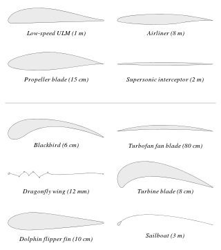
An airfoil or aerofoil is a streamlined body that is capable of generating significantly more lift than drag. Wings, sails and propeller blades are examples of airfoils. Foils of similar function designed with water as the working fluid are called hydrofoils.

In fluid dynamics, the lift coefficient is a dimensionless quantity that relates the lift generated by a lifting body to the fluid density around the body, the fluid velocity and an associated reference area. A lifting body is a foil or a complete foil-bearing body such as a fixed-wing aircraft. CL is a function of the angle of the body to the flow, its Reynolds number and its Mach number. The section lift coefficient cl refers to the dynamic lift characteristics of a two-dimensional foil section, with the reference area replaced by the foil chord.

<span class="mw-page-title-main">Parasitic drag</span> Aerodynamic resistance against the motion of an object

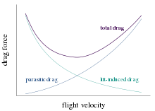
Parasitic drag, also known as profile drag, is a type of aerodynamic drag that acts on any object when the object is moving through a fluid. Parasitic drag is a combination of form drag and skin friction drag. It affects all objects regardless of whether they are capable of generating lift.

In continuum mechanics, the Froude number is a dimensionless number defined as the ratio of the flow inertia to the external field. The Froude number is based on the speed–length ratio which he defined as:

dAlemberts paradox

In fluid dynamics, d'Alembert's paradox is a contradiction reached in 1752 by French mathematician Jean le Rond d'Alembert. d'Alembert proved that – for incompressible and inviscid potential flow – the drag force is zero on a body moving with constant velocity relative to the fluid. Zero drag is in direct contradiction to the observation of substantial drag on bodies moving relative to fluids, such as air and water; especially at high velocities corresponding with high Reynolds numbers. It is a particular example of the reversibility paradox.

<span class="mw-page-title-main">Circulation (physics)</span> Line integral of the fluid velocity around a closed curve

In physics, circulation is the line integral of a vector field around a closed curve. In fluid dynamics, the field is the fluid velocity field. In electrodynamics, it can be the electric or the magnetic field.

In fluid dynamics, the pressure coefficient is a dimensionless number which describes the relative pressures throughout a flow field. The pressure coefficient is used in aerodynamics and hydrodynamics. Every point in a fluid flow field has its own unique pressure coefficient, Cp.

In fluid dynamics, drag, sometimes referred to as fluid resistance, is a force acting opposite to the relative motion of any object, moving with respect to a surrounding fluid. This can exist between two fluid layers, two solid surfaces, or between a fluid and solid surface. Drag forces tend to decrease fluid velocity relative to the solid object in the fluid's path.

A drag count is a dimensionless unit used by aerospace engineers. 1 drag count is equal to a of 0.0001.

In fluid mechanics, added mass or virtual mass is the inertia added to a system because an accelerating or decelerating body must move some volume of surrounding fluid as it moves through it. Added mass is a common issue because the object and surrounding fluid cannot occupy the same physical space simultaneously. For simplicity this can be modeled as some volume of fluid moving with the object, though in reality "all" the fluid will be accelerated, to various degrees.

In mechanics and aerodynamics, the drag area of an object represents the effective size of the object as it is "seen" by the fluid flow around it. The drag area is usually expressed as a product where is a representative area of the object, and is the drag coefficient, which represents what shape it has and how streamlined it is.

The Kutta–Joukowski theorem is a fundamental theorem in aerodynamics used for the calculation of lift of an airfoil translating in a uniform fluid at a constant speed so large that the flow seen in the body-fixed frame is steady and unseparated. The theorem relates the lift generated by an airfoil to the speed of the airfoil through the fluid, the density of the fluid and the circulation around the airfoil. The circulation is defined as the line integral around a closed loop enclosing the airfoil of the component of the velocity of the fluid tangent to the loop. It is named after Martin Kutta and Nikolai Zhukovsky who first developed its key ideas in the early 20th century. Kutta–Joukowski theorem is an inviscid theory, but it is a good approximation for real viscous flow in typical aerodynamic applications.

The Cauchy momentum equation is a vector partial differential equation put forth by Cauchy that describes the non-relativistic momentum transport in any continuum.

<span class="mw-page-title-main">Reynolds number</span> Ratio of inertial to viscous forces acting on a liquid

In fluid dynamics, the Reynolds number is a dimensionless quantity that helps predict fluid flow patterns in different situations by measuring the ratio between inertial and viscous forces. At low Reynolds numbers, flows tend to be dominated by laminar (sheet-like) flow, while at high Reynolds numbers, flows tend to be turbulent. The turbulence results from differences in the fluid's speed and direction, which may sometimes intersect or even move counter to the overall direction of the flow. These eddy currents begin to churn the flow, using up energy in the process, which for liquids increases the chances of cavitation.

Blade element momentum theory is a theory that combines both blade element theory and momentum theory. It is used to calculate the local forces on a propeller or wind-turbine blade. Blade element theory is combined with momentum theory to alleviate some of the difficulties in calculating the induced velocities at the rotor.

Skin friction drag is a type of aerodynamic or hydrodynamic drag, which is resistant force exerted on an object moving in a fluid. Skin friction drag is caused by the viscosity of fluids and is developed from laminar drag to turbulent drag as a fluid moves on the surface of an object. Skin friction drag is generally expressed in terms of the Reynolds number, which is the ratio between inertial force and viscous force.

References