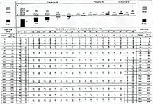
Example for the DIN ISO 2768-2 tolerance table. This is just one example for linear tolerances for a 100 mm value. This is just one of the 8 defined ranges (30–120mm).
Engineering tolerance is the permissible limit or limits of variation in:
Dimensions, properties, or conditions may have some variation without significantly affecting functioning of systems, machines, structures, etc. A variation beyond the tolerance (for example, a temperature that is too hot or too cold) is said to be noncompliant, rejected, or exceeding the tolerance.
Considerations when setting tolerances
A primary concern is to determine how wide the tolerances may be without affecting other factors or the outcome of a process. This can be by the use of scientific principles, engineering knowledge, and professional experience. Experimental investigation is very useful to investigate the effects of tolerances: Design of experiments, formal engineering evaluations, etc.
A good set of engineering tolerances in a specification, by itself, does not imply that compliance with those tolerances will be achieved. Actual production of any product (or operation of any system) involves some inherent variation of input and output. Measurement error and statistical uncertainty are also present in all measurements. With a normal distribution, the tails of measured values may extend well beyond plus and minus three standard deviations from the process average. Appreciable portions of one (or both) tails might extend beyond the specified tolerance.
The choice of tolerances is also affected by the intended statistical sampling plan and its characteristics such as the Acceptable Quality Level. This relates to the question of whether tolerances must be extremely rigid (high confidence in 100% conformance) or whether some small percentage of being out-of-tolerance may sometimes be acceptable.
An alternative view of tolerances
Genichi Taguchi and others have suggested that traditional two-sided tolerancing is analogous to "goal posts" in a football game: It implies that all data within those tolerances are equally acceptable. The alternative is that the best product has a measurement which is precisely on target. There is an increasing loss which is a function of the deviation or variability from the target value of any design parameter. The greater the deviation from target, the greater is the loss. This is described as the Taguchi loss function or quality loss function, and it is the key principle of an alternative system called inertial tolerancing.
Research and development work conducted by M. Pillet and colleagues[1] at the Savoy University has resulted in industry-specific adoption.[2] Recently the publishing of the French standard NFX 04-008 has allowed further consideration by the manufacturing community.
Mechanical component tolerance
Summary of basic size, fundamental deviation and IT grades compared to minimum and maximum sizes of the shaft and hole
Dimensional tolerance is related to, but different from fit in mechanical engineering, which is a designed-in clearance or interference between two parts. Tolerances are assigned to parts for manufacturing purposes, as boundaries for acceptable build. No machine can hold dimensions precisely to the nominal value, so there must be acceptable degrees of variation. If a part is manufactured, but has dimensions that are out of tolerance, it is not a usable part according to the design intent. Tolerances can be applied to any dimension. The commonly used terms are:
Basic size
The nominal diameter of the shaft (or bolt) and the hole. This is, in general, the same for both components.
Lower deviation
The difference between the minimum possible component size and the basic size.
Upper deviation
The difference between the maximum possible component size and the basic size.
Fundamental deviation
The minimum difference in size between a component and the basic size.
This is identical to the upper deviation for shafts and the lower deviation for holes.[3]If the fundamental deviation is greater than zero, the bolt will always be smaller than the basic size and he hole will always be wider. Fundamental deviation is a form of allowance, rather than tolerance.
International Tolerance grade
This is a standardised measure of the maximum difference in size between the component and the basic size (see below).
For example, if a shaft with a nominal diameter of 10mm is to have a sliding fit within a hole, the shaft might be specified with a tolerance range from 9.964 to 10mm (i.e., a zero fundamental deviation, but a lower deviation of 0.036mm) and the hole might be specified with a tolerance range from 10.04mm to 10.076mm (0.04mm fundamental deviation and 0.076mm upper deviation). This would provide a clearance fit of somewhere between 0.04mm (largest shaft paired with the smallest hole, called the Maximum Material Condition - MMC) and 0.112mm (smallest shaft paired with the largest hole, Least Material Condition - LMC). In this case the size of the tolerance range for both the shaft and hole is chosen to be the same (0.036mm), meaning that both components have the same International Tolerance grade but this need not be the case in general.
When no other tolerances are provided, the machining industry uses the following standard tolerances:[4][5]
1 decimal place
(.x):
±0.2"
2 decimal places
(.0x):
±0.01"
3 decimal places
(.00x):
±0.005"
4 decimal places
(.000x):
±0.0005"
Limits and fits establish in 1980, not corresponding to the current ISO tolerances
When designing mechanical components, a system of standardized tolerances called International Tolerance grades are often used. The standard (size) tolerances are divided into two categories: hole and shaft. They are labelled with a letter (capitals for holes and lowercase for shafts) and a number. For example: H7 (hole, tapped hole, or nut) and h7 (shaft or bolt). H7/h6 is a very common standard tolerance which gives a tight fit. The tolerances work in such a way that for a hole H7 means that the hole should be made slightly larger than the base dimension (in this case for an ISO fit 10+0.015−0, meaning that it may be up to 0.015mm larger than the base dimension, and 0mm smaller). The actual amount bigger/smaller depends on the base dimension. For a shaft of the same size, h6 would mean 10+0−0.009, which means the shaft may be as small as 0.009mm smaller than the base dimension and 0mm larger. This method of standard tolerances is also known as Limits and Fits and can be found in ISO 286-1:2010 (Link to ISO catalog).
The table below summarises the International Tolerance (IT) grades and the general applications of these grades:
Measuring Tools
Material
IT Grade
01
0
1
2
3
4
5
6
7
8
9
10
11
12
13
14
15
16
Fits
Large Manufacturing Tolerances
An analysis of fit by statistical interference is also extremely useful: It indicates the frequency (or probability) of parts properly fitting together.
Electrical component tolerance
An electrical specification might call for a resistor with a nominal value of 100 Ω (ohms), but will also state a tolerance such as "±1%". This means that any resistor with a value in the range 99–101Ω is acceptable. For critical components, one might specify that the actual resistance must remain within tolerance within a specified temperature range, over a specified lifetime, and so on.
Many commercially available resistors and capacitors of standard types, and some small inductors, are often marked with coloured bands to indicate their value and the tolerance. High-precision components of non-standard values may have numerical information printed on them.
Low tolerance means only a small deviation from the components given value, when new, under normal operating conditions and at room temperature. Higher tolerance means the component will have a wider range of possible values.
↑ C. Brown, Walter; K. Brown, Ryan (2011). Print Reading for Industry, 10th edition. The Goodheart-Wilcox Company, Inc. p.37. ISBN978-1-63126-051-3.
↑ 2, 3 and 4 decimal places quoted from page 29 of "Machine Tool Practices", 6th edition, by R.R.;Kibbe, J.E.;Neely, R.O.;Meyer & W.T.;White, ISBN0-13-270232-0, 2nd printing, copyright 1999, 1995, 1991, 1987, 1982 and 1979 by Prentice Hall. (All four places, including the single decimal place, are common knowledge in the field, although a reference for the single place could not be found.)
↑ According to Chris McCauley, Editor-In-Chief of Industrial Press' Machinery's Handbook: Standard Tolerance "…does not appear to originate with any of the recent editions (24-28) of Machinery's Handbook, although those tolerances may have been mentioned somewhere in one of the many old editions of the Handbook." (4/24/2009 8:47 AM)
In measurement technology and metrology, calibration is the comparison of measurement values delivered by a device under test with those of a calibration standard of known accuracy. Such a standard could be another measurement device of known accuracy, a device generating the quantity to be measured such as a voltage, a sound tone, or a physical artifact, such as a meter ruler.
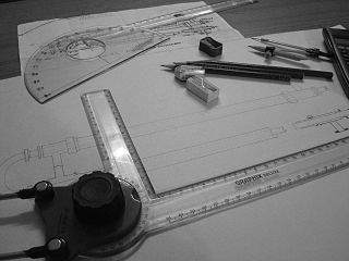
An engineering drawing is a type of technical drawing that is used to convey information about an object. A common use is to specify the geometry necessary for the construction of a component and is called a detail drawing. Usually, a number of drawings are necessary to completely specify even a simple component. These drawings are linked together by a "master drawing." This "master drawing" is more commonly known as an assembly drawing. The assembly drawing gives the drawing numbers of the subsequent detailed components, quantities required, construction materials and possibly 3D images that can be used to locate individual items. Although mostly consisting of pictographic representations, abbreviations and symbols are used for brevity and additional textual explanations may also be provided to convey the necessary information.
Geometric dimensioning and tolerancing (GD&T) is a system for defining and communicating engineering tolerances via a symbolic language on engineering drawings and computer-generated 3D models that describes a physical object's nominal geometry and the permissible variation thereof. GD&T is used to define the nominal geometry of parts and assemblies, the allowable variation in size, form, orientation, and location of individual features, and how features may vary in relation to one another such that a component is considered satisfactory for its intended use. Dimensional specifications define the nominal, as-modeled or as-intended geometry, while tolerance specifications define the allowable physical variation of individual features of a part or assembly.
The Unified Thread Standard (UTS) defines a standard thread form and series—along with allowances, tolerances, and designations—for screw threads commonly used in the United States and Canada. It is the main standard for bolts, nuts, and a wide variety of other threaded fasteners used in these countries. It has the same 60° profile as the ISO metric screw thread, but the characteristic dimensions of each UTS thread were chosen as an inch fraction rather than a millimeter value. The UTS is currently controlled by ASME/ANSI in the United States.
A screw thread is a helical structure used to convert between rotational and linear movement or force. A screw thread is a ridge wrapped around a cylinder or cone in the form of a helix, with the former being called a straight thread and the latter called a tapered thread. A screw thread is the essential feature of the screw as a simple machine and also as a threaded fastener.
A go/no-go gauge refers to an inspection tool used to check a workpiece against its allowed tolerances via a go/no-go test. Its name is derived from two tests: the check involves the workpiece having to pass one test (go) and fail the other (no-go).
An interference fit, also known as a pressed fit or friction fit, is a form of fastening between two tightfitting mating parts that produces a joint which is held together by friction after the parts are pushed together.
The process capability index, or process capability ratio, is a statistical measure of process capability: the ability of an engineering process to produce an output within specification limits. The concept of process capability only holds meaning for processes that are in a state of statistical control. This means it cannot account for deviations which are not expected, such as misaligned, damaged, or worn equipment. Process capability indices measure how much "natural variation" a process experiences relative to its specification limits, and allows different processes to be compared to how well an organization controls them. Somewhat counterintuitively, higher index values indicate better performance, with zero indicating high deviation.
Roundness is the measure of how closely the shape of an object approaches that of a mathematically perfect circle. Roundness applies in two dimensions, such as the cross sectional circles along a cylindrical object such as a shaft or a cylindrical roller for a bearing. In geometric dimensioning and tolerancing, control of a cylinder can also include its fidelity to the longitudinal axis, yielding cylindricity. The analogue of roundness in three dimensions is sphericity.
The ISO metric screw thread is the most commonly used type of general-purpose screw thread worldwide. They were one of the first international standards agreed when the International Organization for Standardization (ISO) was set up in 1947.
An IT grade is an internationally accepted code system for tolerances on linear dimensions. Such code systems may be used to produce interchangeable parts. In engineering, the word tolerance refers to a range of allowable dimensions or values. Standard tolerance grades are a group of tolerances for linear sizes characterized by a common identifier. For SI measurements, a system of tolerance grades defined in ISO 286 is frequently used and identified by the letters IT followed by a number specifying how precise the requirements are, relative to the nominal size of a part.
When two probability distributions overlap, statistical interference exists. Knowledge of the distributions can be used to determine the likelihood that one parameter exceeds another, and by how much.
Engineering fits are generally used as part of geometric dimensioning and tolerancing when a part or assembly is designed. In engineering terms, the "fit" is the clearance between two mating parts, and the size of this clearance determines whether the parts can, at one end of the spectrum, move or rotate independently from each other or, at the other end, are temporarily or permanently joined. Engineering fits are generally described as a "shaft and hole" pairing, but are not necessarily limited to just round components. ISO is the internationally accepted standard for defining engineering fits, but ANSI is often still used in North America.
In engineering and machining, an allowance is a planned deviation between an exact dimension and a nominal or theoretical dimension, or between an intermediate-stage dimension and an intended final dimension. The unifying abstract concept is that a certain amount of difference allows for some known factor of compensation or interference. For example, an area of excess metal may be left because it is needed to complete subsequent machining. Common cases are listed below. An allowance, which is a planned deviation from an ideal, is contrasted with a tolerance, which accounts for expected but unplanned deviations.
The distinction between real value and nominal value occurs in many fields. From a philosophical viewpoint, nominal value represents an accepted condition, which is a goal or an approximation, as opposed to the real value, which is always present.
Tolerance analysis is the general term for activities related to the study of accumulated variation in mechanical parts and assemblies. Its methods may be used on other types of systems subject to accumulated variation, such as mechanical and electrical systems. Engineers analyze tolerances for the purpose of evaluating geometric dimensioning and tolerancing (GD&T). Methods include 2D tolerance stacks, 3D Monte Carlo simulations, and datum conversions.
ISO 128 is an international standard (ISO), about the general principles of presentation in technical drawings, specifically the graphical representation of objects on technical drawings.
ISO 965 is an International Organization for Standardization (ISO) standard for metric screw thread tolerances. It specifies the basic profile for ISO general purpose metric screw threads (M) conforming to ISO 261.
Preferred metric sizes are a set of international standards and de facto standards that are designed to make using the metric system easier and simpler, especially in engineering and construction practices. One of the methods used to arrive at these preferred sizes is the use of preferred numbers and convenient numbers, such as the Renard series and 1-2-5 series, to limit the number of different sizes of components needed.
Geometrical Product Specification and Verification (GPS&V) is a set of ISO standards developed by ISO Technical Committee 213. The aim of those standards is to develop a common language to specify macro geometry and micro-geometry of products or parts of products so that the language can be used consistently worldwide.
This page is based on this Wikipedia article Text is available under the CC BY-SA 4.0 license; additional terms may apply. Images, videos and audio are available under their respective licenses.