Related Research Articles

An electrical network is an interconnection of electrical components or a model of such an interconnection, consisting of electrical elements. An electrical circuit is a network consisting of a closed loop, giving a return path for the current. Thus all circuits are networks, but not all networks are circuits. Linear electrical networks, a special type consisting only of sources, linear lumped elements, and linear distributed elements, have the property that signals are linearly superimposable. They are thus more easily analyzed, using powerful frequency domain methods such as Laplace transforms, to determine DC response, AC response, and transient response.

An amplifier, electronic amplifier or (informally) amp is an electronic device that can increase the magnitude of a signal. It is a two-port electronic circuit that uses electric power from a power supply to increase the amplitude of a signal applied to its input terminals, producing a proportionally greater amplitude signal at its output. The amount of amplification provided by an amplifier is measured by its gain: the ratio of output voltage, current, or power to input. An amplifier is defined as a circuit that has a power gain greater than one.

Three-phase electric power is a common type of alternating current (AC) used in electricity generation, transmission, and distribution. It is a type of polyphase system employing three wires and is the most common method used by electrical grids worldwide to transfer power.
Capacitive coupling is the transfer of energy within an electrical network or between distant networks by means of displacement current between circuit(s) nodes, induced by the electric field. This coupling can have an intentional or accidental effect.
In electrical engineering, electrical elements are conceptual abstractions representing idealized electrical components, such as resistors, capacitors, and inductors, used in the analysis of electrical networks. All electrical networks can be analyzed as multiple electrical elements interconnected by wires. Where the elements roughly correspond to real components, the representation can be in the form of a schematic diagram or circuit diagram. This is called a lumped-element circuit model. In other cases, infinitesimal elements are used to model the network in a distributed-element model.

In direct-current circuit theory, Norton's theorem, also called the Mayer–Norton theorem, is a simplification that can be applied to networks made of linear time-invariant resistances, voltage sources, and current sources. At a pair of terminals of the network, it can be replaced by a current source and a single resistor in parallel.

As originally stated in terms of direct-current resistive circuits only, Thévenin's theorem states that "Any linear electrical network containing only voltage sources, current sources and resistances can be replaced at terminals A–B by an equivalent combination of a voltage source Vth in a series connection with a resistance Rth."

In electronics, negative resistance (NR) is a property of some electrical circuits and devices in which an increase in voltage across the device's terminals results in a decrease in electric current through it.

A voltage regulator is a system designed to automatically maintain a constant voltage. A voltage regulator may use a simple feed-forward design or may include negative feedback. It may use an electromechanical mechanism, or electronic components. Depending on the design, it may be used to regulate one or more AC or DC voltages.

The input impedance of an electrical network is the measure of the opposition to current (impedance), both static (resistance) and dynamic (reactance), into a load network that is external to the electrical source network. The input admittance is a measure of the load network's propensity to draw current. The source network is the portion of the network that transmits power, and the load network is the portion of the network that consumes power.
In electrical engineering and electronics, a network is a collection of interconnected components. Network analysis is the process of finding the voltages across, and the currents through, all network components. There are many techniques for calculating these values; however, for the most part, the techniques assume linear components. Except where stated, the methods described in this article are applicable only to linear network analysis.
A Colpitts oscillator, invented in 1918 by Canadian-American engineer Edwin H. Colpitts, is one of a number of designs for LC oscillators, electronic oscillators that use a combination of inductors (L) and capacitors (C) to produce an oscillation at a certain frequency. The distinguishing feature of the Colpitts oscillator is that the feedback for the active device is taken from a voltage divider made of two capacitors in series across the inductor.

A voltage source is a two-terminal device which can maintain a fixed voltage. An ideal voltage source can maintain the fixed voltage independent of the load resistance or the output current. However, a real-world voltage source cannot supply unlimited current.
Small-signal modeling is a common analysis technique in electronics engineering used to approximate the behavior of electronic circuits containing nonlinear devices with linear equations. It is applicable to electronic circuits in which the AC signals are small relative to the DC bias currents and voltages. A small-signal model is an AC equivalent circuit in which the nonlinear circuit elements are replaced by linear elements whose values are given by the first-order (linear) approximation of their characteristic curve near the bias point.
A linear circuit is an electronic circuit which obeys the superposition principle. This means that the output of the circuit F(x) when a linear combination of signals ax1(t) + bx2(t) is applied to it is equal to the linear combination of the outputs due to the signals x1(t) and x2(t) applied separately:

A static synchronous compensator (STATCOM), originally known as a static synchronous condenser (STATCON), is a shunt-connected, reactive compensation device used on transmission networks. It uses power electronics to form a voltage-source converter that can act as either a source or sink of reactive AC power to an electricity network. It is a member of the FACTS family of devices.

A variety of types of electrical transformer are made for different purposes. Despite their design differences, the various types employ the same basic principle as discovered in 1831 by Michael Faraday, and share several key functional parts.
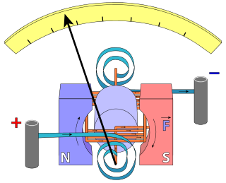
In electrical engineering, current sensing is any one of several techniques used to measure electric current. The measurement of current ranges from picoamps to tens of thousands of amperes. The selection of a current sensing method depends on requirements such as magnitude, accuracy, bandwidth, robustness, cost, isolation or size. The current value may be directly displayed by an instrument, or converted to digital form for use by a monitoring or control system.
Performance modelling is the abstraction of a real system into a simplified representation to enable the prediction of performance. The creation of a model can provide insight into how a proposed or actual system will or does work. This can, however, point towards different things to people belonging to different fields of work.
The black box model of power converter also called behavior model, is a method of system identification to represent the characteristics of power converter, that is regarded as a black box. There are two types of black box model of power converter - when the model includes the load, it is called terminated model, otherwise un-terminated model. The type of black box model of power converter is chosen based on the goal of modeling. This black box model of power converter could be a tool for filter design of a system integrated with power converters.
References
- 1 2 Johnson, D.H. (2003a). "Origins of the equivalent circuit concept: the voltage-source equivalent" (PDF). Proceedings of the IEEE. 91 (4): 636–640. doi:10.1109/JPROC.2003.811716. hdl: 1911/19968 .
- ↑ Richard C. Dorf (1997). The Electrical Engineering Handbook. New York: CRC Press. Fig. 27.4, p. 711. ISBN 978-0-8493-8574-2.
- ↑ Johnson, D.H. (2003b). "Origins of the equivalent circuit concept: the current-source equivalent" (PDF). Proceedings of the IEEE. 91 (5): 817–821. doi:10.1109/JPROC.2003.811795.
- ↑ P.R. Gray; P.J. Hurst; S.H. Lewis; R.G. Meyer (2001). Analysis and Design of Analog Integrated Circuits (Fourth ed.). New York: Wiley. pp. §3.2, p. 172. ISBN 978-0-471-32168-2.
- ↑ Van Haeverbeke, Maxime; Stock, Michiel; De Baets, Bernard (2022). "Equivalent Electrical Circuits and Their Use Across Electrochemical Impedance Spectroscopy Application Domains". IEEE Access. 10: 51363–51379. doi: 10.1109/ACCESS.2022.3174067 . S2CID 248713808.