Ethernet crossover cable

Last updated

An Ethernet crossover cable is a crossover cable for Ethernet used to connect computing devices together directly. It is most often used to connect two devices of the same type, e.g. two computers (via their network interface controllers) or two switches to each other. By contrast, straight through patch cables are used to connect devices of different types, such as a computer to a network switch.

Contents

Intentionally crossed wiring in the crossover cable connects the transmit signals at one end to the receive signals at the other end.

Many network devices today support auto MDI-X (aka "auto crossover") capability, wherein a patch cable can be used in place of a crossover cable, or vice versa, and the receive and transmit signals are reconfigured automatically within the device to yield a working connection.

Motivation

8P8C modular crossover adapter Crossover Adapter DSC01805.JPG
8P8C modular crossover adapter

The 10BASE-T and 100BASE-TX Ethernet standards use one wire pair for transmission in each direction. This requires that the transmit pair of each device be connected to the receive pair of the device on the other end. The 10BASE-T standard was devised to be used with existing twisted pair cable installations with straight-through connections.

When a terminal device (with an MDI port) is connected to a switch or hub, this crossover is done internally in the switch or hub (MDI-X port). A standard straight-through cable is used for this purpose where each pin of the connector on one end is connected to the corresponding pin on the other connector.

One terminal may be connected directly to another without the use of a switch or hub, but in that case, the crossover must be done in the cabling. Since 10BASE-T and 100BASE-TX use pairs 2 and 3, these two pairs must be swapped in the cable. This wiring scheme constitutes a crossover cable. A crossover cable may also be used to connect two hubs or two switches on their upstream ports.

Because the only difference between the T568A and T568B pin and pair assignments are that pairs 2 and 3 are swapped, a crossover cable may be envisioned as a cable with one modular connector following T568A and the other T568B (see TIA/EIA-568 wiring). Such a cable will work for 10BASE-T or 100BASE-TX.

The polarity of each pair is not swapped, but the pairs crossed as a unit: the two wires within each pair are not crossed. [1]

Cable requirement for Ethernet link
To
From
MDIMDI-XAuto MDI-X
MDI crossoverstraightany
MDI-X straightcrossoverany
Auto MDI-X anyanyany

Automatic crossover

Introduced in 1998, this made the distinction between uplink and normal ports and manual selector switches on older hubs and switches obsolete. [2] If one or both of two connected devices has the automatic MDI/MDI-X configuration feature, there is no need for crossover cables.

Although Auto MDI-X was specified as an optional feature in the 1000BASE-T standard, [3] in practice it is implemented widely on most interfaces.

Besides the eventually agreed upon Automatic MDI/MDI-X, this feature may also be referred to by various vendor-specific terms including: Auto uplink and trade, Universal Cable Recognition and Auto Sensing.

1000BASE-T and faster

In a departure from both 10BASE-T and 100BASE-TX, 1000BASE-T and faster use all four cable pairs for simultaneous transmission in both directions through the use of telephone hybrid-like signal handling. For this reason, there are no dedicated transmit and receive pairs. 1000BASE-T and faster require either a straight or one of the crossover variants only for the autonegotiation phase. The physical medium attachment (PMA) sublayer provides identification of each pair and usually continues to work even over cable where the pairs are unusually swapped or crossed. [4]

Fiber

For most optical fiber variants of Ethernet, fibers are used in pairs with one fiber for each direction. The transmitter on one end of the connection needs to be connected to the receiver on the other and vice versa. For this, fiber patch cables with duplex connectors are normally configured as crossover as is the on-premises wiring.[ citation needed ] Thus, a simple connection with two patch cables at each end and a section of fixed cable in the middle has three crossovers in total, resulting in a working connection. Patch cable crossovers can usually be reconfigured very easily by swapping the connectors within a duplex bracket if required.

Pinouts

In practice, it does not matter if non-crossover Ethernet cables are wired as T568A or T568B, just so long as both ends follow the same wiring format. Typical commercially available pre-wired cables can follow either format depending on the manufacturer. What this means is that one manufacturer's cables are wired one way and another's the other way, yet both are correct and will work. In either case, T568A or T568B, a normal (un-crossed) cable will have both ends wired identically according to the layout in either the Connection 1 column or the Connection 2 column.

Half crossed

Crossover cable connecting two MDI ports Ethernet MDI crossover.svg
Crossover cable connecting two MDI ports

Certain equipment or installations, including those in which phone and/or power are mixed with data in the same cable, may require that the "non-data" pairs 1 and 4 (pins 4, 5, 7 and 8) remain un-crossed. This is the most common kind of crossover cable.

Two pairs crossed, two pairs uncrossed 10BASE-T or 100BASE-TX crossover [5]
PinConnection 1: T568A
RJ-45 TIA-568A Right.png
Connection 2: T568B
RJ-45 TIA-568B Right.png
Pins on plug face
signalpaircolorsignalpaircolor
1BI_DA+3 Wire white green stripe.svg
white/green stripe
BI_DB+2 Wire white orange stripe.svg
white/orange stripe
Rj45plug-8p8c.png
2BI_DA-3 Wire green.svg
green solid
BI_DB-2 Wire orange.svg
orange solid
3BI_DB+2 Wire white orange stripe.svg
white/orange stripe
BI_DA+3 Wire white green stripe.svg
white/green stripe
41 Wire blue.svg
blue solid
1 Wire blue.svg
blue solid
51 Wire white blue stripe.svg
white/blue stripe
1 Wire white blue stripe.svg
white/blue stripe
6BI_DB-2 Wire orange.svg
orange solid
BI_DA-3 Wire green.svg
green solid
74 Wire white brown stripe.svg
white/brown stripe
4 Wire white brown stripe.svg
white/brown stripe
84 Wire brown.svg
brown solid
4 Wire brown.svg
brown solid

Fully crossed

All pairs crossed [6]
While this is the only crossover for 1G, it also works for 10M and 100M ethernet
PinTIA/EIA 568-ATIA/EIA 568-B
NormalCrossoverNormalCrossover
1 Wire white green stripe.svg
white/green stripe
Wire white orange stripe.svg
white/orange stripe
Wire white orange stripe.svg
white/orange stripe
Wire white green stripe.svg
white/green stripe
2 Wire green.svg
green solid
Wire orange.svg
orange solid
Wire orange.svg
orange solid
Wire green.svg
green solid
3 Wire white orange stripe.svg
white/orange stripe
Wire white green stripe.svg
white/green stripe
Wire white green stripe.svg
white/green stripe
Wire white orange stripe.svg
white/orange stripe
4 Wire blue.svg
blue solid
Wire white brown stripe.svg
white/brown stripe
Wire blue.svg
blue solid
Wire white brown stripe.svg
white/brown stripe
5 Wire white blue stripe.svg
white/blue stripe
Wire brown.svg
brown solid
Wire white blue stripe.svg
white/blue stripe
Wire brown.svg
brown solid
6 Wire orange.svg
orange solid
Wire green.svg
green solid
Wire green.svg
green solid
Wire orange.svg
orange solid
7 Wire white brown stripe.svg
white/brown stripe
Wire blue.svg
blue solid
Wire white brown stripe.svg
white/brown stripe
Wire blue.svg
blue solid
8 Wire brown.svg
brown solid
Wire white blue stripe.svg
white/blue stripe
Wire brown.svg
brown solid
Wire white blue stripe.svg
white/blue stripe

See also

Related Research Articles

<span class="mw-page-title-main">Ethernet</span> Computer networking technology

Ethernet is a family of wired computer networking technologies commonly used in local area networks (LAN), metropolitan area networks (MAN) and wide area networks (WAN). It was commercially introduced in 1980 and first standardized in 1983 as IEEE 802.3. Ethernet has since been refined to support higher bit rates, a greater number of nodes, and longer link distances, but retains much backward compatibility. Over time, Ethernet has largely replaced competing wired LAN technologies such as Token Ring, FDDI and ARCNET.

100BaseVG is a 100 Mbit/s Ethernet standard specified to run over four pairs of Category 3 cable. It is also called 100VG-AnyLAN because it was defined to carry both Ethernet and Token Ring frame types.

<span class="mw-page-title-main">10BASE2</span> Once-dominant 10 Mbit/s Ethernet standard

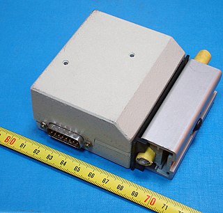
10BASE2 is a variant of Ethernet that uses thin coaxial cable terminated with BNC connectors to build a local area network.

<span class="mw-page-title-main">10BASE5</span> First commercially available variant of Ethernet

10BASE5 was the first commercially available variant of Ethernet. The technology was standardized in 1982 as IEEE 802.3. 10BASE5 uses a thick and stiff coaxial cable up to 500 meters (1,600 ft) in length. Up to 100 stations can be connected to the cable using vampire taps and share a single collision domain with 10 Mbit/s of bandwidth shared among them. The system is difficult to install and maintain.

<span class="mw-page-title-main">Ethernet over twisted pair</span> Ethernet physical layers using twisted-pair cables

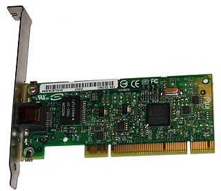
Ethernet over twisted-pair technologies use twisted-pair cables for the physical layer of an Ethernet computer network. They are a subset of all Ethernet physical layers.

<span class="mw-page-title-main">Category 5 cable</span> Unshielded twisted pair communications cable

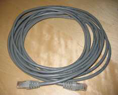
Category 5 cable (Cat 5) is a twisted pair cable for computer networks. Since 2001, the variant commonly in use is the Category 5e specification (Cat 5e). The cable standard provides performance of up to 100 MHz and is suitable for most varieties of Ethernet over twisted pair up to 2.5GBASE-T but more commonly runs at 1000BASE-T speeds. Cat 5 is also used to carry other signals such as telephone and video.

<span class="mw-page-title-main">Fast Ethernet</span> Ethernet standards that carry data at the nominal rate of 100 Mbit/s

In computer networking, Fast Ethernet physical layers carry traffic at the nominal rate of 100 Mbit/s. The prior Ethernet speed was 10 Mbit/s. Of the Fast Ethernet physical layers, 100BASE-TX is by far the most common.

<span class="mw-page-title-main">Gigabit Ethernet</span> Standard for Ethernet networking at a data rate of 1 gigabit per second

In computer networking, Gigabit Ethernet is the term applied to transmitting Ethernet frames at a rate of a gigabit per second. The most popular variant, 1000BASE-T, is defined by the IEEE 802.3ab standard. It came into use in 1999, and has replaced Fast Ethernet in wired local networks due to its considerable speed improvement over Fast Ethernet, as well as its use of cables and equipment that are widely available, economical, and similar to previous standards. The first standard for faster 10 Gigabit Ethernet was approved in 2002.

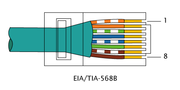
Category 3 cable, commonly known as Cat 3 or station wire, and less commonly known as VG or voice-grade, is an unshielded twisted pair (UTP) cable used in telephone wiring. It is part of a family of standards defined jointly by the Electronic Industries Alliance (EIA) and the Telecommunications Industry Association (TIA) and published in TIA/EIA-568-B.

<span class="mw-page-title-main">Registered jack</span> Telecommunication network interface

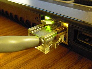
A registered jack (RJ) is a standardized telecommunication network interface for connecting voice and data equipment to a computer service provided by a local exchange carrier or long distance carrier. Registered interfaces were first defined in the Universal Service Ordering Code (USOC) system of the Bell System in the United States for complying with the registration program for customer-supplied telephone equipment mandated by the Federal Communications Commission (FCC) in the 1970s. They were subsequently codified in title 47 of the Code of Federal Regulations Part 68. Registered jack connections began to see use after their invention in 1973 by Bell Labs. The specification includes physical construction, wiring, and signal semantics. Accordingly, registered jacks are primarily named by the letters RJ, followed by two digits that express the type. Additional letter suffixes indicate minor variations. For example, RJ11, RJ14, and RJ25 are the most commonly used interfaces for telephone connections for one-, two-, and three-line service, respectively. Although these standards are legal definitions in the United States, some interfaces are used worldwide.

<span class="mw-page-title-main">Power over Ethernet</span> System for delivering power along with data over an Ethernet cable

Power over Ethernet (PoE) describes any of several standards or ad hoc systems that pass electric power along with data on twisted-pair Ethernet cabling. This allows a single cable to provide both a data connection and enough electricity to power networked devices such as wireless access points (WAPs), IP cameras and VoIP phones.

<span class="mw-page-title-main">Ethernet hub</span> Device for interconnecting Ethernet devices

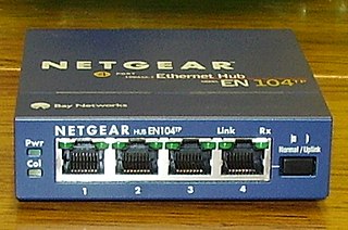
An Ethernet hub, active hub, network hub, repeater hub, multiport repeater, or simply hub is a network hardware device for connecting multiple Ethernet devices together and making them act as a single network segment. It has multiple input/output (I/O) ports, in which a signal introduced at the input of any port appears at the output of every port except the original incoming. A hub works at the physical layer. A repeater hub also participates in collision detection, forwarding a jam signal to all ports if it detects a collision. In addition to standard 8P8C ("RJ45") ports, some hubs may also come with a BNC or an Attachment Unit Interface (AUI) connector to allow connection to legacy 10BASE2 or 10BASE5 network segments.

Autonegotiation is a signaling mechanism and procedure used by Ethernet over twisted pair by which two connected devices choose common transmission parameters, such as speed, duplex mode, and flow control. In this process, the connected devices first share their capabilities regarding these parameters and then choose the highest performance transmission mode they both support.

<span class="mw-page-title-main">Medium-dependent interface</span> Interface between a network device and the data link it communicates over

A medium-dependent interface (MDI) describes the interface in a computer network from a physical-layer implementation to the physical medium used to carry the transmission. Ethernet over twisted pair also defines a medium-dependent interface – crossover (MDI-X) interface. Auto–MDI-X ports on newer network interfaces detect if the connection would require a crossover and automatically choose the MDI or MDI-X configuration to complement the other end of the link.

<span class="mw-page-title-main">Patch cable</span> Cable used to connect electronic or optical devices

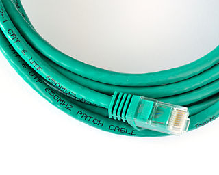
A patch cable, patch cord or patch lead is an electrical or fiber-optic cable used to connect one electronic or optical device to another for signal routing. Devices of different types are connected with patch cords.

<span class="mw-page-title-main">Ethernet physical layer</span> Electrical or optical properties between network devices

The physical-layer specifications of the Ethernet family of computer network standards are published by the Institute of Electrical and Electronics Engineers (IEEE), which defines the electrical or optical properties and the transfer speed of the physical connection between a device and the network or between network devices. It is complemented by the MAC layer and the logical link layer. An implementation of a specific physical layer is commonly referred to as PHY.

<span class="mw-page-title-main">Modular connector</span> Electrical connector commonly used in telephone and computer networks

A modular connector is a type of electrical connector for cords and cables of electronic devices and appliances, such as in computer networking, telecommunication equipment, and audio headsets.

Networking cable is a piece of networking hardware used to connect one network device to other network devices or to connect two or more computers to share devices such as printers or scanners. Different types of network cables, such as coaxial cable, optical fiber cable, and twisted pair cables, are used depending on the network's topology, protocol, and size. The devices can be separated by a few meters or nearly unlimited distances.

ANSI/TIA-568 is a technical standard for commercial building cabling for telecommunications products and services. The title of the standard is Commercial Building Telecommunications Cabling Standard and is published by the Telecommunications Industry Association (TIA), a body accredited by the American National Standards Institute (ANSI).

<span class="mw-page-title-main">OPEN Alliance SIG</span>

The OPEN Alliance is a non-profit, special interest group (SIG) of mainly automotive industry and technology providers collaborating to encourage wide scale adoption of Ethernet-based communication as the standard in automotive networking applications.

References

  1. Charles E. Spurgeon (2000). Ethernet: the Definitive Guide . O'Reilly Media. p.  247. ISBN   978-1-56592-660-8.
  2. Daniel Dove (February 1998). "1000BASE-T Automatic Crossover Algorithm" (PDF). Presentation to IEEE 802.3ab working group. Retrieved June 17, 2011.
  3. Clause "40.4.4 Automatic MDI/MDI-X Configuration" in IEEE 802.3-2008: ( "IEEE 802.3-2008, Part 3" (PDF). 2010-06-22. p. 192. Retrieved 2011-02-07. Implementation of an automatic MDI/MDI-X configuration is optional for 1000BASE-T devices.)
  4. IEEE 802.3-2012 40.1.4 Signaling
  5. Crossover Cable for 10BASE-T and 100BASE-TX
  6. IEEE 802.3 40.8.2 Crossover function