Continuum mechanics is a branch of mechanics that deals with the deformation of and transmission of forces through materials modeled as a continuous medium rather than as discrete particles. The French mathematician Augustin-Louis Cauchy was the first to formulate such models in the 19th century.

Flight dynamics is the science of air vehicle orientation and control in three dimensions. The three critical flight dynamics parameters are the angles of rotation in three dimensions about the vehicle's center of gravity (cg), known as pitch, roll and yaw. These are collectively known as aircraft attitude, often principally relative to the atmospheric frame in normal flight, but also relative to terrain during takeoff or landing, or when operating at low elevation. The concept of attitude is not specific to fixed-wing aircraft, but also extends to rotary aircraft such as helicopters, and dirigibles, where the flight dynamics involved in establishing and controlling attitude are entirely different.

In continuum mechanics, stress is a physical quantity that describes forces present during deformation. For example, an object being pulled apart, such as a stretched elastic band, is subject to tensile stress and may undergo elongation. An object being pushed together, such as a crumpled sponge, is subject to compressive stress and may undergo shortening. The greater the force and the smaller the cross-sectional area of the body on which it acts, the greater the stress. Stress has dimension of force per area, with SI units of newtons per square meter (N/m2) or pascal (Pa).
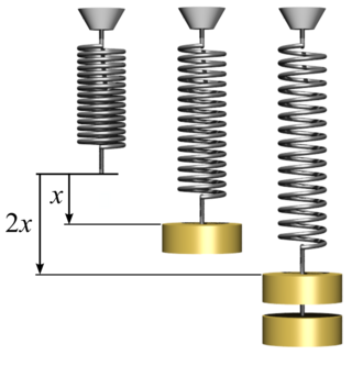
In physics, Hooke's law is an empirical law which states that the force needed to extend or compress a spring by some distance scales linearly with respect to that distance—that is, Fs = kx, where k is a constant factor characteristic of the spring, and x is small compared to the total possible deformation of the spring. The law is named after 17th-century British physicist Robert Hooke. He first stated the law in 1676 as a Latin anagram. He published the solution of his anagram in 1678 as: ut tensio, sic vis. Hooke states in the 1678 work that he was aware of the law since 1660.
Structural analysis is a branch of solid mechanics which uses simplified models for solids like bars, beams and shells for engineering decision making. Its main objective is to determine the effect of loads on the physical structures and their components. In contrast to theory of elasticity, the models used in structure analysis are often differential equations in one spatial variable. Structures subject to this type of analysis include all that must withstand loads, such as buildings, bridges, aircraft and ships. Structural analysis uses ideas from applied mechanics, materials science and applied mathematics to compute a structure's deformations, internal forces, stresses, support reactions, velocity, accelerations, and stability. The results of the analysis are used to verify a structure's fitness for use, often precluding physical tests. Structural analysis is thus a key part of the engineering design of structures.
In the physical science of dynamics, rigid-body dynamics studies the movement of systems of interconnected bodies under the action of external forces. The assumption that the bodies are rigid simplifies analysis, by reducing the parameters that describe the configuration of the system to the translation and rotation of reference frames attached to each body. This excludes bodies that display fluid, highly elastic, and plastic behavior.

D'Alembert's principle, also known as the Lagrange–d'Alembert principle, is a statement of the fundamental classical laws of motion. It is named after its discoverer, the French physicist and mathematician Jean le Rond d'Alembert, and Italian-French mathematician Joseph Louis Lagrange. D'Alembert's principle generalizes the principle of virtual work from static to dynamical systems by introducing forces of inertia which, when added to the applied forces in a system, result in dynamic equilibrium.
In statics and structural mechanics, a structure is statically indeterminate when the equilibrium equations – force and moment equilibrium conditions – are insufficient for determining the internal forces and reactions on that structure.
In mechanics, virtual work arises in the application of the principle of least action to the study of forces and movement of a mechanical system. The work of a force acting on a particle as it moves along a displacement is different for different displacements. Among all the possible displacements that a particle may follow, called virtual displacements, one will minimize the action. This displacement is therefore the displacement followed by the particle according to the principle of least action.
The work of a force on a particle along a virtual displacement is known as the virtual work.

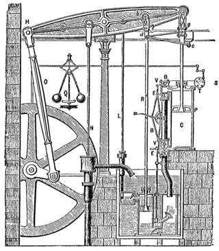
Euler–Bernoulli beam theory is a simplification of the linear theory of elasticity which provides a means of calculating the load-carrying and deflection characteristics of beams. It covers the case corresponding to small deflections of a beam that is subjected to lateral loads only. By ignoring the effects of shear deformation and rotatory inertia, it is thus a special case of Timoshenko–Ehrenfest beam theory. It was first enunciated circa 1750, but was not applied on a large scale until the development of the Eiffel Tower and the Ferris wheel in the late 19th century. Following these successful demonstrations, it quickly became a cornerstone of engineering and an enabler of the Second Industrial Revolution.
As one of the methods of structural analysis, the direct stiffness method, also known as the matrix stiffness method, is particularly suited for computer-automated analysis of complex structures including the statically indeterminate type. It is a matrix method that makes use of the members' stiffness relations for computing member forces and displacements in structures. The direct stiffness method is the most common implementation of the finite element method (FEM). In applying the method, the system must be modeled as a set of simpler, idealized elements interconnected at the nodes. The material stiffness properties of these elements are then, through matrix mathematics, compiled into a single matrix equation which governs the behaviour of the entire idealized structure. The structure’s unknown displacements and forces can then be determined by solving this equation. The direct stiffness method forms the basis for most commercial and free source finite element software.
The finite element method (FEM) is a powerful technique originally developed for numerical solution of complex problems in structural mechanics, and it remains the method of choice for complex systems. In the FEM, the structural system is modeled by a set of appropriate finite elements interconnected at discrete points called nodes. Elements may have physical properties such as thickness, coefficient of thermal expansion, density, Young's modulus, shear modulus and Poisson's ratio.
The Unit dummy force method provides a convenient means for computing displacements in structural systems. It is applicable for both linear and non-linear material behaviours as well as for systems subject to environmental effects, and hence more general than Castigliano's second theorem.

A crash simulation is a virtual recreation of a destructive crash test of a car or a highway guard rail system using a computer simulation in order to examine the level of safety of the car and its occupants. Crash simulations are used by automakers during computer-aided engineering (CAE) analysis for crashworthiness in the computer-aided design (CAD) process of modelling new cars. During a crash simulation, the kinetic energy, or energy of motion, that a vehicle has before the impact is transformed into deformation energy, mostly by plastic deformation (plasticity) of the car body material, at the end of the impact.
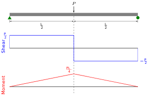
In solid mechanics, a bending moment is the reaction induced in a structural element when an external force or moment is applied to the element, causing the element to bend. The most common or simplest structural element subjected to bending moments is the beam. The diagram shows a beam which is simply supported at both ends; the ends can only react to the shear loads. Other beams can have both ends fixed ; therefore each end support has both bending moments and shear reaction loads. Beams can also have one end fixed and one end simply supported. The simplest type of beam is the cantilever, which is fixed at one end and is free at the other end. In reality, beam supports are usually neither absolutely fixed nor absolutely rotating freely.
Multibody system is the study of the dynamic behavior of interconnected rigid or flexible bodies, each of which may undergo large translational and rotational displacements.

Structural engineering depends upon a detailed knowledge of loads, physics and materials to understand and predict how structures support and resist self-weight and imposed loads. To apply the knowledge successfully structural engineers will need a detailed knowledge of mathematics and of relevant empirical and theoretical design codes. They will also need to know about the corrosion resistance of the materials and structures, especially when those structures are exposed to the external environment.
In classical mechanics, the Udwadia–Kalaba formulation is a method for deriving the equations of motion of a constrained mechanical system. The method was first described by Anatolii Fedorovich Vereshchagin for the particular case of robotic arms, and later generalized to all mechanical systems by Firdaus E. Udwadia and Robert E. Kalaba in 1992. The approach is based on Gauss's principle of least constraint. The Udwadia–Kalaba method applies to both holonomic constraints and nonholonomic constraints, as long as they are linear with respect to the accelerations. The method generalizes to constraint forces that do not obey D'Alembert's principle.
Dynamic Substructuring (DS) is an engineering tool used to model and analyse the dynamics of mechanical systems by means of its components or substructures. Using the dynamic substructuring approach one is able to analyse the dynamic behaviour of substructures separately and to later on calculate the assembled dynamics using coupling procedures. Dynamic substructuring has several advantages over the analysis of the fully assembled system:
In computational mechanics, Guyan reduction, also known as static condensation, is a dimensionality reduction method which reduces the number of degrees of freedom by ignoring the inertial terms of the equilibrium equations and expressing the unloaded degrees of freedom in terms of the loaded degrees of freedom.


