Fracture

Last updated

Ductile failure of a metallic specimen strained axially DuctileFailure.jpg
Ductile failure of a metallic specimen strained axially

Fracture is the appearance of a crack or complete separation of an object or material into two or more pieces under the action of stress. The fracture of a solid usually occurs due to the development of certain displacement discontinuity surfaces within the solid. If a displacement develops perpendicular to the surface, it is called a normal tensile crack or simply a crack; if a displacement develops tangentially, it is called a shear crack, slip band, or dislocation . [1]

Contents

Brittle fractures occur without any apparent deformation before fracture. Ductile fractures occur after visible deformation. Fracture strength, or breaking strength, is the stress when a specimen fails or fractures. The detailed understanding of how a fracture occurs and develops in materials is the object of fracture mechanics.

Strength

Stress vs. strain curve typical of aluminum
Ultimate tensile strength
Yield strength
Proportional limit stress
Fracture
Offset strain (typically 0.2%) Stress v strain Aluminum 2.png
Stress vs. strain curve typical of aluminum
  1. Ultimate tensile strength
  2. Yield strength
  3. Proportional limit stress
  4. Fracture
  5. Offset strain (typically 0.2%)

Fracture strength, also known as breaking strength, is the stress at which a specimen fails via fracture. [2] This is usually determined for a given specimen by a tensile test, which charts the stress–strain curve (see image). The final recorded point is the fracture strength.

Ductile materials have a fracture strength lower than the ultimate tensile strength (UTS), whereas in brittle materials the fracture strength is equivalent to the UTS. [2] If a ductile material reaches its ultimate tensile strength in a load-controlled situation, [Note 1] it will continue to deform, with no additional load application, until it ruptures. However, if the loading is displacement-controlled, [Note 2] the deformation of the material may relieve the load, preventing rupture.

The statistics of fracture in random materials have very intriguing behavior, and was noted by the architects and engineers quite early. Indeed, fracture or breakdown studies might be the oldest physical science studies, which still remain intriguing and very much alive. Leonardo da Vinci, more than 500 years ago, observed that the tensile strengths of nominally identical specimens of iron wire decrease with increasing length of the wires (see e.g., [3] for a recent discussion). Similar observations were made by Galileo Galilei more than 400 years ago. This is the manifestation of the extreme statistics of failure (bigger sample volume can have larger defects due to cumulative fluctuations where failures nucleate and induce lower strength of the sample). [4]

Types

There are two types of fractures: brittle and ductile fractures respectively without or with plastic deformation prior to failure.

Brittle

Brittle fracture in glass Glass fracture.jpg
Brittle fracture in glass
Fracture of an aluminum crank arm of a bicycle, where the bright areas display a brittle fracture, and the dark areas show fatigue fracture Pedalarm Bruch.jpg
Fracture of an aluminum crank arm of a bicycle, where the bright areas display a brittle fracture, and the dark areas show fatigue fracture

In brittle fracture, no apparent plastic deformation takes place before fracture. Brittle fracture typically involves little energy absorption and occurs at high speeds—up to 2,133.6 m/s (7,000 ft/s) in steel. [5] In most cases brittle fracture will continue even when loading is discontinued. [6]

In brittle crystalline materials, fracture can occur by cleavage as the result of tensile stress acting normal to crystallographic planes with low bonding (cleavage planes). In amorphous solids, by contrast, the lack of a crystalline structure results in a conchoidal fracture, with cracks proceeding normal to the applied tension.

The fracture strength (or micro-crack nucleation stress) of a material was first theoretically estimated by Alan Arnold Griffith in 1921:

where: –

Brittle cleavage fracture surface from a scanning electron microscope Sprodbruch.jpg
Brittle cleavage fracture surface from a scanning electron microscope
is the Young's modulus of the material,
is the surface energy, and
is the micro-crack length (or equilibrium distance between atomic centers in a crystalline solid).

On the other hand, a crack introduces a stress concentration modeled by Inglis's equation [7]

(For sharp cracks)

where:

is the loading stress,
is half the length of the crack, and
is the radius of curvature at the crack tip.

Putting these two equations together gets

Sharp cracks (small ) and large defects (large ) both lower the fracture strength of the material.

Recently, scientists have discovered supersonic fracture, the phenomenon of crack propagation faster than the speed of sound in a material. [8] This phenomenon was recently also verified by experiment of fracture in rubber-like materials.

The basic sequence in a typical brittle fracture is: introduction of a flaw either before or after the material is put in service, slow and stable crack propagation under recurring loading, and sudden rapid failure when the crack reaches critical crack length based on the conditions defined by fracture mechanics. [6] Brittle fracture may be avoided by controlling three primary factors: material fracture toughness (Kc), nominal stress level (σ), and introduced flaw size (a). [5] Residual stresses, temperature, loading rate, and stress concentrations also contribute to brittle fracture by influencing the three primary factors. [5]

Under certain conditions, ductile materials can exhibit brittle behavior. Rapid loading, low temperature, and triaxial stress constraint conditions may cause ductile materials to fail without prior deformation. [5]

Ductile

Schematic representation of the steps in ductile fracture (in pure tension) Ductile fracture upd.png
Schematic representation of the steps in ductile fracture (in pure tension)

In ductile fracture, extensive plastic deformation (necking) takes place before fracture. The terms "rupture" and "ductile rupture" describe the ultimate failure of ductile materials loaded in tension. The extensive plasticity causes the crack to propagate slowly due to the absorption of a large amount of energy before fracture. [9] [10]

Ductile fracture surface of 6061-T6 aluminum Ductile Fracture Surface 6061-T6 Al SEM.png
Ductile fracture surface of 6061-T6 aluminum

Because ductile rupture involves a high degree of plastic deformation, the fracture behavior of a propagating crack as modelled above changes fundamentally. Some of the energy from stress concentrations at the crack tips is dissipated by plastic deformation ahead of the crack as it propagates.

The basic steps in ductile fracture are microvoid [11] formation, microvoid coalescence (also known as crack formation), crack propagation, and failure, often resulting in a cup-and-cone shaped failure surface. The microvoids nucleate at various internal discontinuities, such as precipitates, secondary phases, inclusions, and grain boundaries in the material. [11] As local stress increases the microvoids grow, coalesce and eventually form a continuous fracture surface. [11] Ductile fracture is typically transgranular and deformation due to dislocation slip can cause the shear lip characteristic of cup and cone fracture. [12]

The microvoid coalescence results in a dimpled appearance on the fracture surface. The dimple shape is heavily influenced by the type of loading. Fracture under local uniaxial tensile loading usually results in formation of equiaxed dimples. Failures caused by shear will produce elongated or parabolic shaped dimples that point in opposite directions on the matching fracture surfaces. Finally, tensile tearing produces elongated dimples that point in the same direction on matching fracture surfaces. [11]

Characteristics

The manner in which a crack propagates through a material gives insight into the mode of fracture. With ductile fracture a crack moves slowly and is accompanied by a large amount of plastic deformation around the crack tip. A ductile crack will usually not propagate unless an increased stress is applied and generally cease propagating when loading is removed. [6] In a ductile material, a crack may progress to a section of the material where stresses are slightly lower and stop due to the blunting effect of plastic deformations at the crack tip. On the other hand, with brittle fracture, cracks spread very rapidly with little or no plastic deformation. The cracks that propagate in a brittle material will continue to grow once initiated.

Crack propagation is also categorized by the crack characteristics at the microscopic level. A crack that passes through the grains within the material is undergoing transgranular fracture. A crack that propagates along the grain boundaries is termed an intergranular fracture. Typically, the bonds between material grains are stronger at room temperature than the material itself, so transgranular fracture is more likely to occur. When temperatures increase enough to weaken the grain bonds, intergranular fracture is the more common fracture mode. [6]

Testing

Fracture in materials is studied and quantified in multiple ways. Fracture is largely determined by the fracture toughness (), so fracture testing is often done to determine this. The two most widely used techniques for determining fracture toughness are the three-point flexural test and the compact tension test.

By performing the compact tension and three-point flexural tests, one is able to determine the fracture toughness through the following equation:

Where:

is an empirically-derived equation to capture the test sample geometry
is the fracture stress, and
is the crack length.

To accurately attain , the value of must be precisely measured. This is done by taking the test piece with its fabricated notch of length and sharpening this notch to better emulate a crack tip found in real-world materials. [13] Cyclical prestressing the sample can then induce a fatigue crack which extends the crack from the fabricated notch length of to . This value is used in the above equations for determining . [14]

Following this test, the sample can then be reoriented such that further loading of a load (F) will extend this crack and thus a load versus sample deflection curve can be obtained. With this curve, the slope of the linear portion, which is the inverse of the compliance of the material, can be obtained. This is then used to derive f(c/a) as defined above in the equation. With the knowledge of all these variables, can then be calculated.

Ceramics and inorganic glasses

Ceramics and inorganic glasses have fracturing behavior that differ those of metallic materials. Ceramics have high strengths and perform well in high temperatures due to the material strength being independent of temperature. Ceramics have low toughness as determined by testing under a tensile load; often, ceramics have values that are ~5% of that found in metals. [14] However, as demonstrated by Faber and Evans, fracture toughness can be predicted and improved with crack deflection around second phase particles. [15] Ceramics are usually loaded in compression in everyday use, so the compressive strength is often referred to as the strength; this strength can often exceed that of most metals. However, ceramics are brittle and thus most work done revolves around preventing brittle fracture. Due to how ceramics are manufactured and processed, there are often preexisting defects in the material introduce a high degree of variability in the Mode I brittle fracture. [14] Thus, there is a probabilistic nature to be accounted for in the design of ceramics. The Weibull distribution predicts the survival probability of a fraction of samples with a certain volume that survive a tensile stress sigma, and is often used to better assess the success of a ceramic in avoiding fracture.

Fiber bundles

To model fracture of a bundle of fibers, the Fiber Bundle Model was introduced by Thomas Pierce in 1926 as a model to understand the strength of composite materials. [16] The bundle consists of a large number of parallel Hookean springs of identical length and each having identical spring constants. They have however different breaking stresses. All these springs are suspended from a rigid horizontal platform. The load is attached to a horizontal platform, connected to the lower ends of the springs. When this lower platform is absolutely rigid, the load at any point of time is shared equally (irrespective of how many fibers or springs have broken and where) by all the surviving fibers. This mode of load-sharing is called Equal-Load-Sharing mode. The lower platform can also be assumed to have finite rigidity, so that local deformation of the platform occurs wherever springs fail and the surviving neighbor fibers have to share a larger fraction of that transferred from the failed fiber. The extreme case is that of local load-sharing model, where load of the failed spring or fiber is shared (usually equally) by the surviving nearest neighbor fibers. [4]

Disasters

Failures caused by brittle fracture have not been limited to any particular category of engineered structure. [5] Though brittle fracture is less common than other types of failure, the impacts to life and property can be more severe. [5] The following notable historic failures were attributed to brittle fracture:

Computational fracture mechanics

Virtually every area of engineering has been significantly impacted by computers, and fracture mechanics is no exception. Since there are so few actual problems with closed-form analytical solutions, numerical modelling has become an essential tool in fracture analysis. There are literally hundreds of configurations for which stress-intensity solutions have been published, the majority of which were derived from numerical models. The J integral and crack-tip-opening displacement (CTOD) calculations are two more increasingly popular elastic-plastic studies. Additionally, experts are using cutting-edge computational tools to study unique issues such ductile crack propagation, dynamic fracture, and fracture at interfaces. The exponential rise in computational fracture mechanics applications is essentially the result of quick developments in computer technology. [17]

Most used computational numerical methods are finite element and boundary integral equation methods. Other methods include stress and displacement matching, element crack advance in which latter two come under Traditional Methods in Computational Fracture Mechanics.

Fine Mesh done in Rectangular area in Ansys software (Finite Element Method) Meshing in Finite Element Analysis.jpg
Fine Mesh done in Rectangular area in Ansys software (Finite Element Method)

The finite element method

The structures are divided into discrete elements of 1-D beam, 2-D plane stress or plane strain, 3-D bricks or tetrahedron types. The continuity of the elements are enforced using the nodes. [17]

The boundary integral equation method

In this method, the surface is divided into two regions: a region where displacements are specified Su and region with tractions are specified ST . With given boundary conditions, the stresses, strains, and displacements within the body can all theoretically be solved for, along with the tractions on Su and the displacements on ST. It is a very powerful technique to find the unknown tractions and displacements. [17]

Traditional methods in computational fracture mechanics

These methods are used to determine the fracture mechanics parameters using numerical analysis. [17] Some of the traditional methods in computational fracture mechanics, which were commonly used in the past, have been replaced by newer and more advanced techniques. The newer techniques are considered to be more accurate and efficient, meaning they can provide more precise results and do so more quickly than the older methods. Not all traditional methods have been completely replaced, as they can still be useful in certain scenarios, but they may not be the most optimal choice for all applications.

Some of the traditional methods in computational fracture mechanics are:

See also

Notes

  1. A simple load-controlled tensile situation would be to support a specimen from above, and hang a weight from the bottom end. The load on the specimen is then independent of its deformation.
  2. A simple displacement-controlled tensile situation would be to attach a very stiff jack to the ends of a specimen. As the jack extends, it controls the displacement of the specimen; the load on the specimen is dependent on the deformation.

Related Research Articles

<span class="mw-page-title-main">Ductility</span> Degree to which a material under stress irreversibly deforms before failure

Ductility is a mechanical property commonly described as a material's amenability to drawing. In materials science, ductility is defined by the degree to which a material can sustain plastic deformation under tensile stress before failure. Ductility is an important consideration in engineering and manufacturing. It defines a material's suitability for certain manufacturing operations and its capacity to absorb mechanical overload. Some metals that are generally described as ductile include gold and copper, while platinum is the most ductile of all metals in pure form. However, not all metals experience ductile failure as some can be characterized with brittle failure like cast iron. Polymers generally can be viewed as ductile materials as they typically allow for plastic deformation.

In engineering, deformation refers to the change in size or shape of an object. Displacements are the absolute change in position of a point on the object. Deflection is the relative change in external displacements on an object. Strain is the relative internal change in shape of an infinitesimal cube of material and can be expressed as a non-dimensional change in length or angle of distortion of the cube. Strains are related to the forces acting on the cube, which are known as stress, by a stress-strain curve. The relationship between stress and strain is generally linear and reversible up until the yield point and the deformation is elastic. The linear relationship for a material is known as Young's modulus. Above the yield point, some degree of permanent distortion remains after unloading and is termed plastic deformation. The determination of the stress and strain throughout a solid object is given by the field of strength of materials and for a structure by structural analysis.

<span class="mw-page-title-main">Stress–strain curve</span> Curve representing a materials response to applied forces

In engineering and materials science, a stress–strain curve for a material gives the relationship between stress and strain. It is obtained by gradually applying load to a test coupon and measuring the deformation, from which the stress and strain can be determined. These curves reveal many of the properties of a material, such as the Young's modulus, the yield strength and the ultimate tensile strength.

The field of strength of materials typically refers to various methods of calculating the stresses and strains in structural members, such as beams, columns, and shafts. The methods employed to predict the response of a structure under loading and its susceptibility to various failure modes takes into account the properties of the materials such as its yield strength, ultimate strength, Young's modulus, and Poisson's ratio. In addition, the mechanical element's macroscopic properties such as its length, width, thickness, boundary constraints and abrupt changes in geometry such as holes are considered.

<span class="mw-page-title-main">Compressive strength</span> Capacity of a material or structure to withstand loads tending to reduce size

In mechanics, compressive strength is the capacity of a material or structure to withstand loads tending to reduce size. In other words, compressive strength resists compression, whereas tensile strength resists tension. In the study of strength of materials, tensile strength, compressive strength, and shear strength can be analyzed independently.

<span class="mw-page-title-main">Toughness</span> Material ability to absorb energy and plastically deform without fracturing

In materials science and metallurgy, toughness is the ability of a material to absorb energy and plastically deform without fracturing. Toughness is the strength with which the material opposes rupture. One definition of material toughness is the amount of energy per unit volume that a material can absorb before rupturing. This measure of toughness is different from that used for fracture toughness, which describes the capacity of materials to resist fracture. Toughness requires a balance of strength and ductility.

<span class="mw-page-title-main">Fracture mechanics</span> Study of propagation of cracks in materials

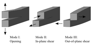
Fracture mechanics is the field of mechanics concerned with the study of the propagation of cracks in materials. It uses methods of analytical solid mechanics to calculate the driving force on a crack and those of experimental solid mechanics to characterize the material's resistance to fracture.

Thermal shock is a phenomenon characterized by a rapid change in temperature that results in a transient mechanical load on an object. The load is caused by the differential expansion of different parts of the object due to the temperature change. This differential expansion can be understood in terms of strain, rather than stress. When the strain exceeds the tensile strength of the material, it can cause cracks to form and eventually lead to structural failure.

<span class="mw-page-title-main">Work hardening</span> Strengthening a material through plastic deformation

In materials science, work hardening, also known as strain hardening, is the strengthening of a metal or polymer by plastic deformation. Work hardening may be desirable, undesirable, or inconsequential, depending on the context.

<span class="mw-page-title-main">Fracture toughness</span> Stress intensity factor at which a cracks propagation increases drastically

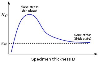
In materials science, fracture toughness is the critical stress intensity factor of a sharp crack where propagation of the crack suddenly becomes rapid and unlimited. A component's thickness affects the constraint conditions at the tip of a crack with thin components having plane stress conditions and thick components having plane strain conditions. Plane strain conditions give the lowest fracture toughness value which is a material property. The critical value of stress intensity factor in mode I loading measured under plane strain conditions is known as the plane strain fracture toughness, denoted . When a test fails to meet the thickness and other test requirements that are in place to ensure plane strain conditions, the fracture toughness value produced is given the designation . Fracture toughness is a quantitative way of expressing a material's resistance to crack propagation and standard values for a given material are generally available.

The J-integral represents a way to calculate the strain energy release rate, or work (energy) per unit fracture surface area, in a material. The theoretical concept of J-integral was developed in 1967 by G. P. Cherepanov and independently in 1968 by James R. Rice, who showed that an energetic contour path integral was independent of the path around a crack.

<span class="mw-page-title-main">Fracture (geology)</span> Geologic discontinuity feature, often a joint or fault

A fracture is any separation in a geologic formation, such as a joint or a fault that divides the rock into two or more pieces. A fracture will sometimes form a deep fissure or crevice in the rock. Fractures are commonly caused by stress exceeding the rock strength, causing the rock to lose cohesion along its weakest plane. Fractures can provide permeability for fluid movement, such as water or hydrocarbons. Highly fractured rocks can make good aquifers or hydrocarbon reservoirs, since they may possess both significant permeability and fracture porosity.

Methods have been devised to modify the yield strength, ductility, and toughness of both crystalline and amorphous materials. These strengthening mechanisms give engineers the ability to tailor the mechanical properties of materials to suit a variety of different applications. For example, the favorable properties of steel result from interstitial incorporation of carbon into the iron lattice. Brass, a binary alloy of copper and zinc, has superior mechanical properties compared to its constituent metals due to solution strengthening. Work hardening has also been used for centuries by blacksmiths to introduce dislocations into materials, increasing their yield strengths.

<span class="mw-page-title-main">Microvoid coalescence</span>

Microvoid coalescence (MVC) is a high energy microscopic fracture mechanism observed in the majority of metallic alloys and in some engineering plastics.

Material failure theory is an interdisciplinary field of materials science and solid mechanics which attempts to predict the conditions under which solid materials fail under the action of external loads. The failure of a material is usually classified into brittle failure (fracture) or ductile failure (yield). Depending on the conditions most materials can fail in a brittle or ductile manner or both. However, for most practical situations, a material may be classified as either brittle or ductile.

In solid mechanics, the Johnson–Holmquist damage model is used to model the mechanical behavior of damaged brittle materials, such as ceramics, rocks, and concrete, over a range of strain rates. Such materials usually have high compressive strength but low tensile strength and tend to exhibit progressive damage under load due to the growth of microfractures.

<span class="mw-page-title-main">Size effect on structural strength</span> Deviation with the scale in the theories of elastic or plastic structures

According to the classical theories of elastic or plastic structures made from a material with non-random strength (ft), the nominal strength (σN) of a structure is independent of the structure size (D) when geometrically similar structures are considered. Any deviation from this property is called the size effect. For example, conventional strength of materials predicts that a large beam and a tiny beam will fail at the same stress if they are made of the same material. In the real world, because of size effects, a larger beam will fail at a lower stress than a smaller beam.

Polymer fracture is the study of the fracture surface of an already failed material to determine the method of crack formation and extension in polymers both fiber reinforced and otherwise. Failure in polymer components can occur at relatively low stress levels, far below the tensile strength because of four major reasons: long term stress or creep rupture, cyclic stresses or fatigue, the presence of structural flaws and stress-cracking agents. Formations of submicroscopic cracks in polymers under load have been studied by x ray scattering techniques and the main regularities of crack formation under different loading conditions have been analyzed. The low strength of polymers compared to theoretically predicted values are mainly due to the many microscopic imperfections found in the material. These defects namely dislocations, crystalline boundaries, amorphous interlayers and block structure can all lead to the non-uniform distribution of mechanical stress.

<span class="mw-page-title-main">Crack tip opening displacement</span>

Crack tip opening displacement (CTOD) or is the distance between the opposite faces of a crack tip at the 90° intercept position. The position behind the crack tip at which the distance is measured is arbitrary but commonly used is the point where two 45° lines, starting at the crack tip, intersect the crack faces. The parameter is used in fracture mechanics to characterize the loading on a crack and can be related to other crack tip loading parameters such as the stress intensity factor and the elastic-plastic J-integral.

In materials science, toughening refers to the process of making a material more resistant to the propagation of cracks. When a crack propagates, the associated irreversible work in different materials classes is different. Thus, the most effective toughening mechanisms differ among different materials classes. The crack tip plasticity is important in toughening of metals and long-chain polymers. Ceramics have limited crack tip plasticity and primarily rely on different toughening mechanisms.

References

  1. Cherepanov, G.P., Mechanics of Brittle Fracture
  2. 1 2 Degarmo, E. Paul; Black, J T.; Kohser, Ronald A. (2003), Materials and Processes in Manufacturing (9th ed.), Wiley, p. 32, ISBN   0-471-65653-4.
  3. Lund, J. R.; Bryne, J. P., Civil. Eng. and Env. Syst. 18 (2000) 243
  4. 1 2 Chakrabarti, Bikas K. (December 2017). "Story of the Developments in Statistical Physics of Fracture, Breakdown and Earthquake: A Personal Account". Reports in Advances of Physical Sciences. 01 (4): 1750013. doi: 10.1142/S242494241750013X . ISSN   2424-9424. CC-BY icon.svg Text was copied from this source, which is available under a Creative Commons Attribution 4.0 International License.
  5. 1 2 3 4 5 6 7 8 9 Rolfe, John M. Barsom, Stanley T. (1999). Fracture and fatigue control in structures: applications of fracture mechanics (3 ed.). West Conshohocken, Pa.: ASTM. ISBN   0803120826.{{cite book}}: CS1 maint: multiple names: authors list (link)
  6. 1 2 3 4 5 6 7 Campbell, F.C., ed. (2012). Fatigue and fracture: understanding the basics. Materials Park, Ohio: ASM International. ISBN   978-1615039760.
  7. Inglis, Charles E. (1913). "Stresses in a plate due to the presence of cracks and sharp corners" (PDF). Transactions of the Institution of Naval Architects. 55: 219–230.
  8. C. H. Chen; H. P. Zhang; J. Niemczura; K. Ravi-Chandar; M. Marder (November 2011). "Scaling of crack propagation in rubber sheets". Europhysics Letters. 96 (3): 36009. Bibcode:2011EL.....9636009C. doi:10.1209/0295-5075/96/36009. S2CID   5975098.
  9. Perez, Nestor (2016). Fracture Mechanics (2nd ed.). Springer. ISBN   978-3319249971.
  10. Callister, William D. Jr. (2018). Materials science and engineering: an introduction (8th ed.). Wiley. pp. 236–237. ISBN   978-1-119-40539-9. OCLC   992798630.
  11. 1 2 3 4 Ewalds, H. L. (1985). Fracture mechanics. R. J. H. Wanhill. London: E. Arnold. ISBN   0-7131-3515-8. OCLC   14377078.
  12. Askeland, Donald R. (January 2015). The science and engineering of materials. Wright, Wendelin J. (Seventh ed.). Boston, MA. pp. 236–237. ISBN   978-1-305-07676-1. OCLC   903959750.{{cite book}}: CS1 maint: location missing publisher (link)
  13. An improved semi-analytical solution for stress at round-tip notches, a closer look
  14. 1 2 3 Courtney, Thomas H. (2000), Mechanical behavior of materials (3nd ed.), McGraw Hill, ISBN   1-57766-425-6.
  15. Faber, K. T.; Evans, A. G. (1 April 1983). "Crack deflection processes—I. Theory". Acta Metallurgica. 31 (4): 565–576. doi:10.1016/0001-6160(83)90046-9. ISSN   0001-6160.
  16. Pierce, F. T., J. Textile Indust. 17 (1926) 355
  17. 1 2 3 4 Anderson, T. L. (2005). Fracture mechanics : fundamentals and applications (3rd ed.). Boca Raton, FL. ISBN   978-1-4200-5821-5. OCLC   908077872.{{cite book}}: CS1 maint: location missing publisher (link)

Further reading