Free body diagram

Last updated
Block on a ramp and corresponding free body diagram of the block. Free body diagram2.svg
Block on a ramp and corresponding free body diagram of the block.

In physics and engineering, a free body diagram (FBD; also called a force diagram) [1] is a graphical illustration used to visualize the applied forces, moments, and resulting reactions on a body in a given condition. It depicts a body or connected bodies with all the applied forces and moments, and reactions, which act on the body(ies). The body may consist of multiple internal members (such as a truss), or be a compact body (such as a beam). A series of free bodies and other diagrams may be necessary to solve complex problems. Sometimes in order to calculate the resultant force graphically the applied forces are arranged as the edges of a polygon of forces [2] or force polygon (see § Polygon of forces).

Contents

Purpose

Free body diagrams are used to visualize forces and moments applied to a body and to calculate reactions in mechanics problems. These diagrams are frequently used both to determine the loading of individual structural components and to calculate internal forces within a structure. They are used by most engineering disciplines from Biomechanics to Structural Engineering. [3] [4] In the educational environment, a free body diagram is an important step in understanding certain topics, such as statics, dynamics and other forms of classical mechanics.

Features

A free body diagram is not a scaled drawing, it is a diagram. The symbols used in a free body diagram depends upon how a body is modeled. [5]

Free body diagrams consist of:

The number of forces and moments shown depends upon the specific problem and the assumptions made. Common assumptions are neglecting air resistance and friction and assuming rigid body action.

In statics all forces and moments must balance to zero; the physical interpretation is that if they do not, the body is accelerating and the principles of statics do not apply. In dynamics the resultant forces and moments can be non-zero.

Free body diagrams may not represent an entire physical body. Portions of a body can be selected for analysis. This technique allows calculation of internal forces, making them appear external, allowing analysis. This can be used multiple times to calculate internal forces at different locations within a physical body.

For example, a gymnast performing the iron cross: modeling the ropes and person allows calculation of overall forces (body weight, neglecting rope weight, breezes, buoyancy, electrostatics, relativity, rotation of the earth, etc.). Then remove the person and show only one rope; you get force direction. Then only looking at the person the forces on the hand can be calculated. Now only look at the arm to calculate the forces and moments at the shoulders, and so on until the component you need to analyze can be calculated.

Modeling the body

A body may be modeled in three ways:

use a diagram to explain where non specific defence are found and whether they are chemical or just barriers


What is included

An FBD represents the body of interest and the external forces acting on it.

Often a provisional free body is drawn before everything is known. The purpose of the diagram is to help to determine magnitude, direction, and point of application of external loads. When a force is originally drawn, its length may not indicate the magnitude. Its line may not correspond to the exact line of action. Even its orientation may not be correct.

External forces known to have negligible effect on the analysis may be omitted after careful consideration (e.g. buoyancy forces of the air in the analysis of a chair, or atmospheric pressure on the analysis of a frying pan).

External forces acting on an object may include friction, gravity, normal force, drag, tension, or a human force due to pushing or pulling. When in a non-inertial reference frame (see coordinate system, below), fictitious forces, such as centrifugal pseudoforce are appropriate.

At least one coordinate system is always included, and chosen for convenience. Judicious selection of a coordinate system can make defining the vectors simpler when writing the equations of motion or statics. The x direction may be chosen to point down the ramp in an inclined plane problem, for example. In that case the friction force only has an x component, and the normal force only has a y component. The force of gravity would then have components in both the x and y directions: mgsin(θ) in the x and mgcos(θ) in the y, where θ is the angle between the ramp and the horizontal.

Exclusions

A free body diagram should not show:

Analysis

In an analysis, a free body diagram is used by summing all forces and moments (often accomplished along or about each of the axes). When the sum of all forces and moments is zero, the body is at rest or moving and/or rotating at a constant velocity, by Newton's first law. If the sum is not zero, then the body is accelerating in a direction or about an axis according to Newton's second law.

Forces not aligned to an axis

Angled force (F) redefined into components along axes (Fx) and (Fy) Vector components.JPG
Angled force (F) redefined into components along axes (Fx) and (Fy)

Determining the sum of the forces and moments is straightforward if they are aligned with coordinate axes, but it is more complex if some are not. It is convenient to use the components of the forces, in which case the symbols ΣFx and ΣFy are used instead of ΣF (the variable M is used for moments).

Forces and moments that are at an angle to a coordinate axis can be rewritten as two vectors that are equivalent to the original (or three, for three dimensional problems)—each vector directed along one of the axes (Fx) and (Fy).

Example: A block on an inclined plane

A simple free-body diagram, shown above, of a block on a ramp, illustrates this.

Some care is needed in interpreting the diagram.

Polygon of forces

A force polygon for the forces P1 to P6 applied to point O Polygon of forces.png
A force polygon for the forces P1 to P6 applied to point O

In the case of two applied forces, their sum (resultant force) can be found graphically using a parallelogram of forces.

To graphically determine the resultant force of multiple forces, the acting forces can be arranged as edges of a polygon by attaching the beginning of one force vector to the end of another in an arbitrary order. Then the vector value of the resultant force would be determined by the missing edge of the polygon. [2] In the diagram, the forces P1 to P6 are applied to the point O. The polygon is constructed starting with P1 and P2 using the parallelogram of forces (vertex a). The process is repeated (adding P3 yields the vertex b, etc.). The remaining edge of the polygon O-e represents the resultant force R.

Kinetic diagram

Free body and kinetic diagrams of an inclined block Kinetic diagram of inclined block.svg
Free body and kinetic diagrams of an inclined block

In dynamics a kinetic diagram is a pictorial device used in analyzing mechanics problems when there is determined to be a net force and/or moment acting on a body. They are related to and often used with free body diagrams, but depict only the net force and moment rather than all of the forces being considered.

Kinetic diagrams are not required to solve dynamics problems; their use in teaching dynamics is argued against by some [6] in favor of other methods that they view as simpler. They appear in some dynamics texts [7] but are absent in others. [8]

See also

Related Research Articles

<span class="mw-page-title-main">Force</span> Influence that can change motion of an object

In physics, a force is an influence that can cause an object to change its velocity, i.e., to accelerate, meaning a change in speed or direction, unless counterbalanced by other forces. The concept of force makes the everyday notion of pushing or pulling mathematically precise. Because the magnitude and direction of a force are both important, force is a vector quantity. The SI unit of force is the newton (N), and force is often represented by the symbol F.

<span class="mw-page-title-main">Fluid dynamics</span> Aspects of fluid mechanics involving flow

In physics, physical chemistry and engineering, fluid dynamics is a subdiscipline of fluid mechanics that describes the flow of fluids—liquids and gases. It has several subdisciplines, including aerodynamics and hydrodynamics. Fluid dynamics has a wide range of applications, including calculating forces and moments on aircraft, determining the mass flow rate of petroleum through pipelines, predicting weather patterns, understanding nebulae in interstellar space and modelling fission weapon detonation.

<span class="mw-page-title-main">Friction</span> Force resisting sliding motion

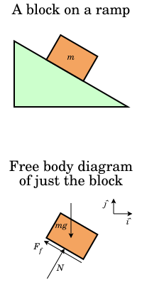
Friction is the force resisting the relative motion of solid surfaces, fluid layers, and material elements sliding against each other. Types of friction include dry, fluid, lubricated, skin, and internal.

<span class="mw-page-title-main">Precession</span> Periodic change in the direction of a rotation axis

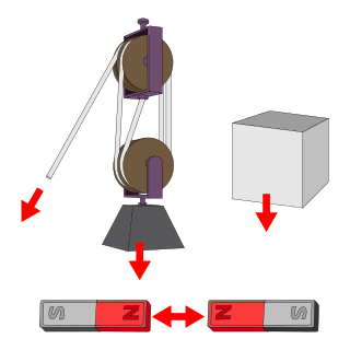
Precession is a change in the orientation of the rotational axis of a rotating body. In an appropriate reference frame it can be defined as a change in the first Euler angle, whereas the third Euler angle defines the rotation itself. In other words, if the axis of rotation of a body is itself rotating about a second axis, that body is said to be precessing about the second axis. A motion in which the second Euler angle changes is called nutation. In physics, there are two types of precession: torque-free and torque-induced.

Statics is the branch of classical mechanics that is concerned with the analysis of force and torque acting on a physical system that does not experience an acceleration, but rather is in equilibrium with its environment.

<span class="mw-page-title-main">Work (physics)</span> Process of energy transfer to an object via force application through displacement

In physics, work is the energy transferred to or from an object via the application of force along a displacement. In its simplest form, for a constant force aligned with the direction of motion, the work equals the product of the force strength and the distance traveled. A force is said to do positive work if when applied it has a component in the direction of the displacement of the point of application. A force does negative work if it has a component opposite to the direction of the displacement at the point of application of the force.

<span class="mw-page-title-main">Center of mass</span> Unique point where the weighted relative position of the distributed mass sums to zero

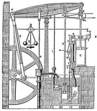
In physics, the center of mass of a distribution of mass in space is the unique point at any given time where the weighted relative position of the distributed mass sums to zero. This is the point to which a force may be applied to cause a linear acceleration without an angular acceleration. Calculations in mechanics are often simplified when formulated with respect to the center of mass. It is a hypothetical point where the entire mass of an object may be assumed to be concentrated to visualise its motion. In other words, the center of mass is the particle equivalent of a given object for application of Newton's laws of motion.

<span class="mw-page-title-main">Net force</span> Vector sum of all forces acting upon a particle or body

In mechanics, the net force is the sum of all the forces acting on an object. For example, if two forces are acting upon an object in opposite directions, and one force is greater than the other, the forces can be replaced with a single force that is the difference of the greater and smaller force. That force is the net force.

<span class="mw-page-title-main">Rigid body</span> Physical object which does not deform when forces or moments are exerted on it

In physics, a rigid body, also known as a rigid object, is a solid body in which deformation is zero or negligible. The distance between any two given points on a rigid body remains constant in time regardless of external forces or moments exerted on it. A rigid body is usually considered as a continuous distribution of mass.

<span class="mw-page-title-main">Resultant force</span> Single force representing the combination of all forces acting on a physical body

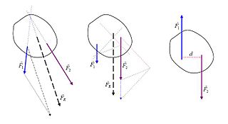
In physics and engineering, a resultant force is the single force and associated torque obtained by combining a system of forces and torques acting on a rigid body via vector addition. The defining feature of a resultant force, or resultant force-torque, is that it has the same effect on the rigid body as the original system of forces. Calculating and visualizing the resultant force on a body is done through computational analysis, or a free body diagram.

<span class="mw-page-title-main">Rigid body dynamics</span> Study of the effects of forces on undeformable bodies

In the physical science of dynamics, rigid-body dynamics studies the movement of systems of interconnected bodies under the action of external forces. The assumption that the bodies are rigid simplifies analysis, by reducing the parameters that describe the configuration of the system to the translation and rotation of reference frames attached to each body. This excludes bodies that display fluid, highly elastic, and plastic behavior.

In mechanics, virtual work arises in the application of the principle of least action to the study of forces and movement of a mechanical system. The work of a force acting on a particle as it moves along a displacement is different for different displacements. Among all the possible displacements that a particle may follow, called virtual displacements, one will minimize the action. This displacement is therefore the displacement followed by the particle according to the principle of least action.

The work of a force on a particle along a virtual displacement is known as the virtual work.

Inverse dynamics is an inverse problem. It commonly refers to either inverse rigid body dynamics or inverse structural dynamics. Inverse rigid-body dynamics is a method for computing forces and/or moments of force (torques) based on the kinematics (motion) of a body and the body's inertial properties. Typically it uses link-segment models to represent the mechanical behaviour of interconnected segments, such as the limbs of humans or animals or the joint extensions of robots, where given the kinematics of the various parts, inverse dynamics derives the minimum forces and moments responsible for the individual movements. In practice, inverse dynamics computes these internal moments and forces from measurements of the motion of limbs and external forces such as ground reaction forces, under a special set of assumptions.

<span class="mw-page-title-main">Rotation around a fixed axis</span> Type of motion

Rotation around a fixed axis or axial rotation is a special case of rotational motion around an axis of rotation fixed, stationary, or static in three-dimensional space. This type of motion excludes the possibility of the instantaneous axis of rotation changing its orientation and cannot describe such phenomena as wobbling or precession. According to Euler's rotation theorem, simultaneous rotation along a number of stationary axes at the same time is impossible; if two rotations are forced at the same time, a new axis of rotation will result.

<span class="mw-page-title-main">Bending moment</span> Force tending to bend a structural element

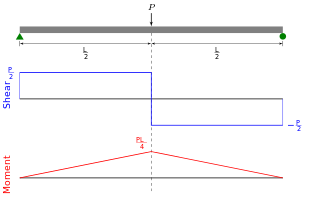
In solid mechanics, a bending moment is the reaction induced in a structural element when an external force or moment is applied to the element, causing the element to bend. The most common or simplest structural element subjected to bending moments is the beam. The diagram shows a beam which is simply supported at both ends; the ends can only react to the shear loads. Other beams can have both ends fixed ; therefore each end support has both bending moments and shear reaction loads. Beams can also have one end fixed and one end simply supported. The simplest type of beam is the cantilever, which is fixed at one end and is free at the other end. In reality, beam supports are usually neither absolutely fixed nor absolutely rotating freely.

In mechanics, a couple is a system of forces with a resultant moment of force but no resultant force.

Vectorial Mechanics (1948) is a book on vector manipulation by Edward Arthur Milne, a highly decorated British astrophysicist and mathematician. Milne states that the text was due to conversations with his then-colleague and erstwhile teacher Sydney Chapman who viewed vectors not merely as a pretty toy but as a powerful weapon of applied mathematics. Milne states that he did not at first believe Chapman, holding on to the idea that "vectors were like a pocket-rule, which needs to be unfolded before it can be applied and used." In time, however, Milne convinces himself that Chapman was right.

In classical mechanics, Euler's laws of motion are equations of motion which extend Newton's laws of motion for point particle to rigid body motion. They were formulated by Leonhard Euler about 50 years after Isaac Newton formulated his laws.

This glossary of physics is a list of definitions of terms and concepts relevant to physics, its sub-disciplines, and related fields, including mechanics, materials science, nuclear physics, particle physics, and thermodynamics. For more inclusive glossaries concerning related fields of science and technology, see Glossary of chemistry terms, Glossary of astronomy, Glossary of areas of mathematics, and Glossary of engineering.

In a broad sense, the term graphic statics is used to describe the technique of solving particular practical problems of statics using graphical means. Actively used in the architecture of the 19th century, the methods of graphic statics were largely abandoned in the second half of the 20th century, primarily due to widespread use of frame structures of steel and reinforced concrete that facilitated analysis based on linear algebra. The beginning of the 21st century was marked by a "renaissance" of the technique driven by its addition to the computer-aided design tools thus enabling the architects to instantly visualize form and forces.

References

  1. "Force Diagrams (Free-body Diagrams)". Western Kentucky University. Archived from the original on 2011-03-17. Retrieved 2011-03-17.
  2. 1 2 Rennie & Law 2019.
  3. Ruina, Andy; Pratap, Rudra (2010). Introduction to Statics and Dynamics (PDF). Oxford University Press. pp. 79–105. Retrieved 2006-08-04.
  4. Hibbeler, R.C. (2007). Engineering Mechanics: Statics & Dynamics (11th ed.). Pearson Prentice Hall. pp. 83–86. ISBN   978-0-13-221509-1.
  5. Puri, Avinash (1996). "The Art of Free-body Diagrams". Physics Education. 31 (3): 155. Bibcode:1996PhyEd..31..155P. doi:10.1088/0031-9120/31/3/015. S2CID   250802652.
  6. Kraige, L. Glenn (16 June 2002), The Role Of The Kinetic Diagram In The Teaching Of Introductory Rigid Body Dynamics Past, Present, And Future, pp. 7.1182.1–7.1182.11
  7. "Stress and Dynamics" (PDF). Retrieved August 5, 2015.
  8. Ruina, Andy; Pratap, Rudra (2002). Introduction to Statics and Dynamics. Oxford University Press. Retrieved September 4, 2019.

Sources

Notes

  1. The line of action is important where moment matters