In digital logic and computing, a counter is a device which stores the number of times a particular event or process has occurred, often in relationship to a clock. The most common type is a sequential digital logic circuit with an input line called the clock and multiple output lines. The values on the output lines represent a number in the binary or BCD number system. Each pulse applied to the clock input increments or decrements the number in the counter.

A multivibrator is an electronic circuit used to implement a variety of simple two-state devices such as relaxation oscillators, timers, latches and flip-flops. The first multivibrator circuit, the astable multivibrator oscillator, was invented by Henri Abraham and Eugene Bloch during World War I. It consisted of two vacuum tube amplifiers cross-coupled by a resistor-capacitor network. They called their circuit a "multivibrator" because its output waveform was rich in harmonics. A variety of active devices can be used to implement multivibrators that produce similar harmonic-rich wave forms; these include transistors, neon lamps, tunnel diodes and others. Although cross-coupled devices are a common form, single-element multivibrator oscillators are also common.
A Costas loop is a phase-locked loop (PLL) based circuit which is used for carrier frequency recovery from suppressed-carrier modulation signals and phase modulation signals. It was invented by John P. Costas at General Electric in the 1950s. Its invention was described as having had "a profound effect on modern digital communications". The primary application of Costas loops is in wireless receivers. Its advantage over other PLL-based detectors is that at small deviations the Costas loop error voltage is as compared to . This translates to double the sensitivity and also makes the Costas loop uniquely suited for tracking Doppler-shifted carriers, especially in OFDM and GPS receivers.

A phase-locked loop or phase lock loop (PLL) is a control system that generates an output signal whose phase is related to the phase of an input signal. There are several different types; the simplest is an electronic circuit consisting of a variable frequency oscillator and a phase detector in a feedback loop. The oscillator's frequency and phase are controlled proportionally by an applied voltage, hence the term voltage-controlled oscillator (VCO). The oscillator generates a periodic signal of a specific frequency, and the phase detector compares the phase of that signal with the phase of the input periodic signal, to adjust the oscillator to keep the phases matched.
In automata theory, sequential logic is a type of logic circuit whose output depends on the present value of its input signals and on the sequence of past inputs, the input history. This is in contrast to combinational logic, whose output is a function of only the present input. That is, sequential logic has state (memory) while combinational logic does not.
A dual modulus prescaler is an electronic circuit used in high-frequency synthesizer designs to overcome the problem of generating narrowly spaced frequencies that are nevertheless too high to be passed directly through the feedback loop of the system. The modulus of a prescaler is its frequency divisor. A dual-modulus prescaler has two separate frequency divisors, usually M and M+1.
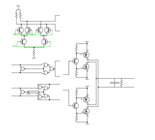
A phase detector or phase comparator is a frequency mixer, analog multiplier or logic circuit that generates a signal which represents the difference in phase between two signal inputs.

In electronics, a voltage divider (also known as a potential divider) is a passive linear circuit that produces an output voltage (Vout) that is a fraction of its input voltage (Vin). Voltage division is the result of distributing the input voltage among the components of the divider. A simple example of a voltage divider is two resistors connected in series, with the input voltage applied across the resistor pair and the output voltage emerging from the connection between them.
A variable frequency oscillator (VFO) in electronics is an oscillator whose frequency can be tuned over some range. It is a necessary component in any tunable radio transmitter and in receivers that works by the superheterodyne principle. The oscillator controls the frequency to which the apparatus is tuned.

A voltage-controlled oscillator (VCO) is an electronic oscillator whose oscillation frequency is controlled by a voltage input. The applied input voltage determines the instantaneous oscillation frequency. Consequently, a VCO can be used for frequency modulation (FM) or phase modulation (PM) by applying a modulating signal to the control input. A VCO is also an integral part of a phase-locked loop. VCOs are used in synthesizers to generate a waveform whose pitch can be adjusted by a voltage determined by a musical keyboard or other input.
In electronic instrumentation and signal processing, a time-to-digital converter (TDC) is a device for recognizing events and providing a digital representation of the time they occurred. For example, a TDC might output the time of arrival for each incoming pulse. Some applications wish to measure the time interval between two events rather than some notion of an absolute time.
In digital circuit design, register-transfer level (RTL) is a design abstraction which models a synchronous digital circuit in terms of the flow of digital signals (data) between hardware registers, and the logical operations performed on those signals.
Direct digital synthesis (DDS) is a method employed by frequency synthesizers used for creating arbitrary waveforms from a single, fixed-frequency reference clock. DDS is used in applications such as signal generation, local oscillators in communication systems, function generators, mixers, modulators, sound synthesizers and as part of a digital phase-locked loop.
In electronics, a frequency multiplier is an electronic circuit that generates an output signal and that output frequency is a harmonic (multiple) of its input frequency. Frequency multipliers consist of a nonlinear circuit that distorts the input signal and consequently generates harmonics of the input signal. A subsequent bandpass filter selects the desired harmonic frequency and removes the unwanted fundamental and other harmonics from the output.

In electronics, a delay-locked loop (DLL) is a pseudo-digital circuit similar to a phase-locked loop (PLL), with the main difference being the absence of an internal voltage-controlled oscillator, replaced by a delay line.
A ring counter is a type of counter composed of flip-flops connected into a shift register, with the output of the last flip-flop fed to the input of the first, making a "circular" or "ring" structure.
A frequency synthesizer is an electronic circuit that generates a range of frequencies from a single reference frequency. Frequency synthesizers are used in many modern devices such as radio receivers, televisions, mobile telephones, radiotelephones, walkie-talkies, CB radios, cable television converter boxes, satellite receivers, and GPS systems. A frequency synthesizer may use the techniques of frequency multiplication, frequency division, direct digital synthesis, frequency mixing, and phase-locked loops to generate its frequencies. The stability and accuracy of the frequency synthesizer's output are related to the stability and accuracy of its reference frequency input. Consequently, synthesizers use stable and accurate reference frequencies, such as those provided by a crystal oscillator.

SN76477 "complex sound generator" is a sound chip produced by Texas Instruments (TI). The chip came to market in 1978, and TI ceased production of the part. A compatible version is identified as ICS76477. The chip is typically used as a sound effects generator in arcade games and toys and for hobby projects. The use of the SN76477 in a musical context is limited by the fact that it was difficult to electronically control the pitch of the produced sound.
A PLL multibit or multibit PLL is a phase-locked loop (PLL) which achieves improved performance compared to a unibit PLL by using more bits. Unibit PLLs use only the most significant bit (MSB) of each counter's output bus to measure the phase, while multibit PLLs use more bits. PLLs are an essential component in telecommunications.

In electronics, flip-flops and latches are circuits that have two stable states that can store state information – a bistable multivibrator. The circuit can be made to change state by signals applied to one or more control inputs and will output its state. It is the basic storage element in sequential logic. Flip-flops and latches are fundamental building blocks of digital electronics systems used in computers, communications, and many other types of systems.


