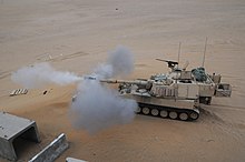
Gun laying is the process of aiming an artillery piece or turret, such as a gun, howitzer, or mortar, on land, at sea, or in air, against surface or aerial targets. It may be laying for either direct fire, where the gun is aimed directly at a target within the line-of-sight of the user, or by indirect fire, where the gun is not aimed directly at a target within the line-of-sight of the user. Indirect fire is determined from the information or data that is collected, calculated, and applied to physical coordinates to identify the location of the target by the user. The term includes automated aiming using, for example, radar-derived target data and computer-controlled guns.
Manual traverse for an Eland armoured car. Gun elevation is controlled by the left traverse wheel, horizontal turret rotation by the right.
Gun laying is a set of actions to align the axis of a gun barrel so that it points in the required direction. This alignment is in the horizontal and vertical planes. A gun is "traversed" (rotated in a horizontal plane) to align it with the target, and "elevated" (moved in the vertical plane) to range it to the target. Gun laying may be for direct fire, where the layer sees the target, or indirect fire, where the target may not be visible from the gun. Gun laying has sometimes been called "training the gun".
Laying in the vertical plane (elevation angle) uses data derived from trials or empirical experience. For any given gun and projectile types, it reflects the distance to the target and the size of the propellant charge. It also incorporates any differences in height between gun and target. With indirect fire, it may allow for other variables as well.
With direct fire, laying in the horizontal plane is merely the line of sight to the target, although the layer may make allowance for the wind, and with rifled guns the sights may compensate for projectile "drift". With indirect fire the horizontal angle is relative to something, typically the gun's aiming point, although with modern electronic sights it may be a north-seeking gyro.
Depending on the gun mount, there is usually a choice of two trajectories that will result in the shot landing in the same spot. The dividing angle between the trajectories is about 45 degrees (usually between 0 degrees and 90 degrees), it varies slightly due to gun dependent factors. Below 45 degrees the trajectory is called "low angle" (or lower register), above 45 degrees is "high angle" (or upper register). The differences are that low angle fire has a shorter time of flight, a lower vertex, and flatter angle of descent.
All guns have carriages or mountings that support the barrel assembly (called the ordnance in some countries). Early guns could only be traversed by moving their entire carriage or mounting, and this lasted with heavy artillery into World War II. Mountings could be fitted into traversing turrets on ships, coast defences or tanks. From circa 1900 field artillery carriages provided traverse without moving the wheels and trail.
The carriage, or mounting, also enabled the barrel to be set at the required elevation angle. With some gun mounts it is possible to depress the gun, i.e., move it in the vertical plane to point it below the horizon. Some guns require a near-horizontal elevation for loading. An essential capability for any elevation mechanism is to prevent the weight of the barrel forcing its heavier end downward. This is greatly helped by having trunnions (around which the elevating mass rotates vertically) at the centre of gravity, although a counterbalance mechanism can be used. It also means the elevation gear has to be strong enough to resist considerable downward pressure but still be easy for the gun layer to use.
Until recoil systems were invented in the late 19th century and integrated into the gun carriage or mount, guns moved substantially backwards when they fired, and had to be moved forward before they could be laid. However, mortars, where the recoil forces were transferred directly into the ground (or water, if mounted on a ship), did not always require such movement. With the adoption of recoil systems for field artillery, it became normal to pivot the saddle on the lower carriage, initially this "top traverse" was only a few degrees but soon offered a full circle, particularly for anti-aircraft guns. The introduction of recoil systems was an important milestone.
The earliest guns were loaded from the muzzle. They were typically little more than bare barrels moved in wagons and placed on the ground for firing, then wooden frames and beds were introduced. Horizontal alignment with the target was by eye, while vertical laying was done by raising the muzzle with timber or digging a hole for the closed end.[1]
Gun carriages were introduced in the 15th century. Two large-diameter wheels, axle-tree and a trail became the standard pattern for field use. The barrel was mounted in a wooden cradle with trunnions to mount it on the carriage. As technology improved, the trunnions became part of the barrel and the cradle was abandoned. Nevertheless, they were relatively large and heavy.[2]
Horizontal alignment was a matter of moving the trail. To achieve the required elevation angle, various arrangements were used. At the simplest, it was wedges or quoins between the breech and the trail, but wooden quadrants, or simple scaffolds mounted on the trail, were also used to support the breech and provided larger choice of elevation angle. Screw elevation devices were also used as early as the 16th century.[3]
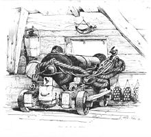
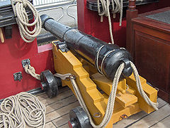
However, naval and some fortress carriages and mounting evolved differently. Field mobility was not required, so large wheels and trails were irrelevant. Headspace below decks was often low. This led to compact carriages, mostly on four small wheels. Obviously, large horizontal traverses were more difficult, but such things were unnecessary when shooting broadside. However, in fortresses wider traverse was required. One solution was platform and slide mountings. Wide traverse was also useful on some shipmounted guns.
Laying required sights. At its simplest, this means nothing more than aiming the guns in the right direction. However, various aids emerged. Horizontal aiming involved sighting along the barrel, this was enhanced by a notch made in the ring around the barrel at the breech end and an 'acorn' on the ring around the muzzle. This was still used in the 19th century in some instances.[4]
The range with a flat trajectory was called 'point blank' range. However, while point blank may have been enough for some purposes, field artillery (whether mobile or static) and guns in fortresses needed longer range. This required ways to measure elevation angles and know the relationship between the elevation angle and the range.
The first recorded device to measure an elevation angle was Niccolò Tartaglia's invention of a gunners' quadrant circa 1545. This device had two arms at right angles connected by an arc marked with angular graduations. One arm was placed in the muzzle, and a plumb bob suspended against the arc showed the elevation angle. This led to many calculations relating elevation angle to range.
The problem was that these calculations assumed what today is called an "in vacuo" trajectory – they made no allowance for air resistance against the projectile. What was needed were range and accuracy trials to determine the actual relationship between range and elevation angle.[5] The practical approach was conducted by William Eldred, Master Gunner at Dover Castle, in gunnery trials in 1613, 1617 and 1622. He used a wide variety of guns, including the culverin, demiculverin, falconet and Saker. From the results of these trials, he produced range tables for elevations up to 10 degrees for each type with a standard propelling charge weight.[6]
A problem affecting gun laying, was the tapered external barrel shape. This affected elevation when the gun was aimed by sighting along the top of the barrel. In the early 17th century, 'dispart sights' compensated for this. This was a piece of metal placed on the muzzle to make the line of sight parallel to the axis of the bore. Another technique involved measuring the depth of the barrel through the touchhole and at the muzzle, the difference being the wedge size needed to compensate for the tapered barrel.[4]
The ballistic pendulum was invented in 1742 by English mathematician Benjamin Robins, and published in his book New Principles of Gunnery, which revolutionized the science of ballistics, as it provided the first way to accurately measure the velocity of a bullet.[7][8]
Robins used the ballistic pendulum to measure projectile velocity in two ways. The first was to attach the gun to the pendulum, and measure the recoil. Since the momentum of the gun is equal to the momentum of the ejecta, and since the projectile was (in those experiments) the large majority of the mass of the ejecta, the velocity of the bullet could be approximated. The second, and more accurate method, was to directly measure the bullet momentum by firing it into the pendulum. Robins experimented with musket balls of around one ounce in mass (30 g), while other contemporaries used his methods with cannon shot of one to three pounds (0.45 to 1.36kg).[8]
The first system to supplant ballistic pendulums with direct measures of projectile speed was invented in 1808, during the Napoleonic Wars and used a rapidly rotating shaft of known speed with two paper disks on it; the bullet was fired through the disks, parallel to the shaft, and the angular difference in the points of impact provided an elapsed time over the distance between the disks. A direct electromechanical clockwork measure appeared in 1840, with a spring-driven clock started and stopped by electromagnets, whose current was interrupted by the bullet passing through two meshes of fine wires, again providing the time to traverse the given distance.[7]
Tangent sights were introduced in the 19th century. These provided the rear sight used with an 'acorn' or similar foresight at the muzzle. The tangent sight was mounted in a bracket beside or behind the breech, the eyepiece (a hole or notch) was atop a vertical bar that moved up and down in the bracket. The bar was marked in yards or degrees. This direct-fire sight was aimed at the target by moving the trail horizontally and elevating or depressing the barrel. By the late 19th century the simple open tangent sights were being replaced by optical telescopes on mounts with an elevation scale and screw aligned to the axis of the bore.[9]
Rifled and breech loadingartillery were introduced from the mid-19th century, notably by William Armstrong, whose gun equipped Royal Navy warships from the 1850s.[10] An important advance in the art of gun laying came with the introduction of the first recoil mechanisms. The barrel recoil was absorbed by hydraulic cylinders and then the barrel was returned to its firing position by a spring that had stored some of the recoil energy.[11] This meant the gun did not have to be repositioned after each time it was fired.
An early prototype incorporating this design feature was built in 1872 by Russian engineer, Vladimir Stepanovich Baranovsky. His 2.5-inch rapid-firing gun was also equipped with a screw breech, a self-cocking firing mechanism and it fired a fixed round (shell and cartridge case together). The recoil mechanism was contained in the gun cradle.
Despite this effort, nothing followed from it, and it was only with the introduction of the French 75 mm in 1897, that recoil systems started to become normal. The gun's barrel slid back on rollers, pushing a piston into an oil-filled cylinder. This action absorbed the recoil progressively as the internal air pressure rose and, at the end of recoil, generated a strong, but decreasing, back pressure that returned the gun forward to its original position. By this time smokeless powder had replaced gunpowder as the standard propellant.
Naval range-finding instruments of 1936.
The first practical rangefinder was developed by Barr & Stroud a pioneering Scottishoptical engineering firm. Archibald Barr and William Stroud became associated from 1888.[12] In 1891 they were approached by the Admiralty to submit a design for a short-base rangefinder for trial, and in 1892 they were awarded with a contract for six of their rangefinders. The device, operated by one person, brought two images from a distance object into coincidence allowing the distance to be calculated from their relative motions. [13]
Eyepiece image of a naval rangefinder, showing the displaced image when not yet adjusted for range.
Now that the barrel remained aligned with the target after firing, the more primitive tangent sight was replaced with the rocking-bar sight for direct-fire sighting. These were installed on QF 4.7-inch Gun Mk I–IVquick firing gun from 1887. The rocking-bar (or 'bar and drum') sight had an elevation scale, could mount a telescope as well as the open sight, and provided a small amount of horizontal deflection. These provided 'independent line of sight' because they enabled data to be set on the mount and the telescope (or open sight) aimed at the target independent of the barrel elevation.
A related problem, particularly for large and longer range guns, was that the wheels could be at different heights due to the slope of the ground, which caused inaccuracy. Before the First World War, the British BL 60-pounder gun was fitted with oscillating (reciprocating) sights, using sighting telescopes, a sight clinometer and range scale as well as a deflection drum for the telescope. These mounts could be cross-leveled, which removed the need for the gun commander to calculate a deflection correction for uneven wheels.[14] Cross-leveling introduced the third axis into laying.
Modern indirect fire dates from the late 19th century. In 1882, Russian Lt Col KG Guk published Field Artillery Fire from Covered Positions that described a better method of indirect laying (instead of aiming points in line with the target). In essence, this was the geometry of using angles to aiming points that could be in any direction relative to the target. The problem was the lack of an azimuth instrument to enable it; clinometers for elevation already existed.
The Germans solved this problem by inventing the Richtfläche, or lining-plane, in about 1890. This was a gun-mounted rotatable open sight, mounted in alignment with the bore, and able to measure large angles from it. Similar designs, usually able to measure angles in a full circle, were widely adopted over the following decade. By the early 1900s the open sight was sometimes replaced by a telescope and the term goniometer had replaced "lining-plane" in English.
The first incontrovertible, documented use of indirect fire in war using Guk's methods, albeit without lining-plane sights was on 26 October 1899 by British gunners during the Second Boer War.[15] Although both sides demonstrated early on in the conflict that could use the technique effectively, in many subsequent battles, British commanders nonetheless ordered artillery to be "less timid" and to move forward to address troops' concerns about their guns abandoning them.[15] The British used improvised gun arcs with howitzers;[16] the sighting arrangements used by the Boers with their German and French guns is unclear.
A 1904 Russian lining plane sight.
Optical sights appeared in the first years of the 20th century, and the German Goerz panoramic sight became the pattern for the rest of the 20th century. They were graduated in degrees and 5 minute intervals, decigrads or mils (4320, 4000 or 6000/6300/6400 to a circle).
A feature of 20th-century laying was the use of one- or two-man laying. The US was notable for using two-man laying, horizontal on one side of the gun, elevation on the other. Most other nations mostly used one-man laying. The laying drill, dealing with all three axes, typically adopted this sequence: "roughly for line, roughly for elevation, cross-level, accurately for line, accurately for elevation".
The other main difference in sighting arrangements was the use of an elevation angle or alternatively the range. This issue became more complicated in World War I when the effects of barrel wear in changing muzzle velocity were fully recognised. This meant that different guns needed a different elevation angle for the same range. This led many armies to use an elevation angle calculated in a battery command post. However, in the 1930s the British adopted calibrating sights in which range was set on the sight, which automatically compensated for the difference of muzzle velocity from standard.
An alternative to this was a 'gun rule' at each gun; in this case the range was set on the rule and an elevation angle read and given to the layer to set on the sight. The issue was finally resolved by the introduction of digital computers in the battery command post that calculated the correct elevation angle for the range and muzzle velocity accurately and quickly.
Apart from calibrating sights, there was no significant difference in field artillery laying arrangements for most of the 20th century. However, in the 1990s new or modified guns started adopting digital sights, following their successful use in the multi-launch rocket system developed in the 1970s. In these the azimuth and elevation were entered manually or automatically into a layers computer, then guided the layer's use of horizontal and elevation controls until the barrel was in the required horizontal and vertical alignment. This computed a correction for the cross level of the gun and used feedback from electro-mechanical devices, such as gyroscopes and electronic clinometers, aligned to the axis of the bore. These devices were subsequently replaced by ring laser gyros.
Coastal and naval gun laying advances
The Range Finder Building, built into the cliff face at St. David's Battery, Bermuda, captured data that was used in the plotting room to produce gun-laying data.
Most coastal artillery was in fixed defences, "fortresses" in some form. Their targets moved in two dimensions, and the gun had to be aimed at the target's future position. Some guns were relatively small calibre and dealt with relatively close targets, others were much larger for long-range targets.
Coast artillery employed direct fire, and until the late 19th century laying had changed little, apart from gaining telescopic sights, over the centuries.
"The position-finder traces the course of the ship, and when the guns are ready to lay, predicts the position the ship will occupy half a minute or more in advance. The dials on the gun floor automatically indicate the range and training to hit the predicted position. When the guns are laid an electric tube (i.e., primer) is inserted and the signal goes up to the observing station that all is ready for firing. The non-commissioned officer in charge of the position-finder watches for the appearance of the ship in the field of view of his telescope, and when she arrives at the cross wires presses a button, and the guns are fired."[17]
It took almost 20 years to get it to full effectiveness, but its general principle became the norm for heavy artillery fire control and laying. Shorter-range guns retained conventional direct-fire laying with telescopes for much longer. In the 20th century, coast artillery, like field and the larger anti-aircraft guns, included corrections for non-standard conditions such as wind and temperature in their calculations.
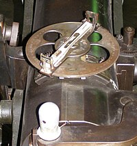
Accurate fire control systems were introduced in the early 20th century. Pictured, a cut-away view of a destroyer. The below decks analog computer is shown in the centre of the drawing and is labelled "Gunnery Calculating Position".
However, ships had a complication compared to land based guns: they were firing from a moving platform. This meant that their laying calculations had to predict the future position of both ship and target. Increasingly sophisticated mechanical calculators were employed for proper gun laying, typically with various spotters and distance measures being sent to a central plotting station deep within the ship. There the fire direction teams fed in the location, speed and direction of the ship and its target, as well as various adjustments for Coriolis effect, weather effects on the air, and other adjustments.
The resulting directions, known as a firing solution, would then be fed back out to the turrets for laying. If the rounds missed, an observer could work out how far they missed by and in which direction, and this information could be fed back into the computer along with any changes in the rest of the information and another shot attempted.
Rudimentary naval fire control systems were first developed around the time of World War I.[18]Arthur Pollen and Frederic Charles Dreyer independently developed the first such systems. Pollen began working on the problem after noting the poor accuracy of naval artillery at a gunnery practice near Malta in 1900.[19]Lord Kelvin, widely regarded as Britain's leading scientist first proposed using an analogue computer to solve the equations which arise from the relative motion of the ships engaged in the battle and the time delay in the flight of the shell to calculate the required trajectory and therefore the direction and elevation of the guns.
Pollen aimed to produce a combined mechanical computer and automatic plot of ranges and rates for use in centralised fire control. To obtain accurate data of the target's position and relative motion, Pollen developed a plotting unit (or plotter) to capture this data. He added a gyroscope to allow for the yaw of the firing ship. Again this required substantial development of the, at the time, primitive gyroscope to provide continuous reliable correction.[20] Trials were carried out in 1905 and 1906, which although completely unsuccessful showed promise. He was encouraged in his efforts by the rapidly rising figure of Admiral Jackie Fisher, Admiral Arthur Knyvet Wilson and the Director of Naval Ordnance and Torpedoes (DNO), John Jellicoe. Pollen continued his work, with tests carried out on Royal Navy warships intermittently.
Meanwhile, a group led by Dreyer designed a similar system. Although both systems were ordered for new and existing ships of the Royal Navy, the Dreyer system eventually found most favour with the Navy in its definitive Mark IV* form. The addition of director control facilitated a full, practicable fire control system for World War I ships, and most RN capital ships were so fitted by mid 1916. The director was high up over the ship where operators had a superior view over any gunlayer in the turrets. It was also able to co-ordinate the fire of the turrets so that their combined fire worked together. This improved aiming and larger optical rangefinders improved the estimate of the enemy's position at the time of firing. The system was eventually replaced by the improved "Admiralty Fire Control Table" for ships built after 1927.
By the 1950s gun turrets were increasingly unmanned, with gun laying controlled remotely from the ship's control centre using inputs from radar and other sources.
Telescopic sights for tanks were adopted before World War II, and these sights usually had a means of aiming off for target movement and graticules marked for different ranges. Tank sights were of two general types. Either the sight was in fixed alignment with the axis of the bore with ranges marked in the sight, and the gunner laid the range mark on the target. Or during laying the gunner physically set the range to offset the axis of the bore from the axis of the sight by the correct amount and laid using the centre mark in the sight.
Some sights had a means of estimating the range, for example using a stadiametric method. Other tanks used an optical coincident range-finder or after World War II, a ranging machine gun. From the 1970s these were replaced by laser range finders. However, tank guns could not be fired accurately while moving until gun stabilisation was introduced. This appeared at the end of World War II. Some were hydraulic, while others used electrical servos. During the 1970s tanks started being fitted with digital computers.
Anti-aircraft gun laying
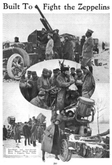
A French anti-aircraft motor battery (motorized AAA battery) that brought down a Zeppelin near Paris. From the journal Horseless Age, 1916.
The need to engage balloons and airships, from both the ground and ships, was recognised at the beginning of the 20th century. Aircraft were soon added to the list and the others fell from significance. Anti-aircraft was direct fire, the layer aiming at the aircraft. However, the target is moving in three dimensions and this makes it a difficult target. The basic issue is that either the layer aims at the target and some mechanism aligns the gun at the future (time of flight) position of the target or the layer aims at the future position of the aircraft. In either case the problem is determining the target's height, speed and direction and being able to 'aim-off' (sometimes called deflection laying) for the anti-aircraft projectile time of flight.
German air attacks on the British Isles began at the beginning of the First World War. Anti-aircraft gunnery was a difficult business. The problem was of successfully aiming a shell to burst close to its target's future position, with various factors affecting the shells' predicted trajectory. This was called deflection gun-laying, 'off-set' angles for range and elevation were set on the gunsight and updated as their target moved. In this method when the sights were on the target, the barrel was pointed at the target's future position. Range and height of the target determined fuze length. The difficulties increased as aircraft performance improved.
The British dealt with range measurement first, when it was realised that range was the key to producing a better fuse setting. This led to the Height/Range Finder (HRF), the first model being the Barr & Stroud UB2, a 2-metre optical coincident rangefinder mounted on a tripod. It measured the distance to the target and the elevation angle, which together gave the height of the aircraft. These were complex instruments and various other methods were also used. The HRF was soon joined by the Height/Fuze Indicator (HFI), this was marked with elevation angles and height lines overlaid with fuze length curves, using the height reported by the HRF operator, the necessary fuse length could be read off.[21]
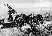
A Canadian anti-aircraft unit of 1918, running to stations.
However, the problem of deflection settings—'aim-off'—required knowing the rate of change in the target's position. Both France and UK introduced tachymetric devices to track targets and produce vertical and horizontal deflection angles. The French Brocq system was electrical, the operator entered the target range and had displays at guns; it was used with their 75mm. The British Wilson-Dalby gun director used a pair of trackers and mechanical tachymetry; the operator entered the fuse length, and deflection angles were read from the instruments.v
In 1925 the British adopted a new instrument developed by Vickers. It was a mechanical analogue computer Predictor AA No 1. Given the target height its operators tracked the target and the predictor produced bearing, quadrant elevation and fuze setting. These were passed electrically to the guns where they were displayed on repeater dials to the layers who 'matched pointers' (target data and the gun's actual data) to lay the guns. This system of repeater electrical dials built on the arrangements introduced by British coast artillery in the 1880s, and coast artillery was the background of many AA officers. Similar systems were adopted in other countries and for example the later Sperry device, designated M3A3 in the US was also used by Britain as the Predictor AA No 2. Height finders were also increasing in size, in Britain, the World War I Barr & Stroud UB 2 (7 feet (2.1m) optical base) was replaced by the UB 7 (7 feet (2.1m) feet optical base) and the UB 10 (18 feet (5.5m) optical base, only used on static AA sites). Goertz in Germany and Levallois in France produced 5 metres (16ft) instruments.[21]
By World War II the situation was largely as follows: for targets up to a few thousand yards away, a smaller-calibre automatic gun was used, with simple sights that enabled a layer to judge the lead based on estimates of target range and speed; for longer-range targets, manually controlled predictors were used to track the target, taking inputs from optical or radar rangefinders, and calculating firing data for the guns, including allowance for wind and temperature.
After World War II predictors changed from being electro-mechanical analogue computers to digital computers, but by this time heavy anti-aircraft guns had been replaced by missiles, but electronics enabled smaller guns to adopt fully automated laying.
See also
Arrow slit– Narrow vertical aperture in a fortificationPages displaying short descriptions of redirect targets
Artillery are ranged weapons that launch munitions far beyond the range and power of infantry firearms. Early artillery development focused on the ability to breach defensive walls and fortifications during sieges, and led to heavy, fairly immobile siege engines. As technology improved, lighter, more mobile field artillery cannons developed for battlefield use. This development continues today; modern self-propelled artillery vehicles are highly mobile weapons of great versatility generally providing the largest share of an army's total firepower.
The howitzer is an artillery weapon that falls between a cannon and a mortar. It is generally aimed lower than a mortar but higher than a cannon. With their long-range capabilities, howitzers can be used to great effect in a battery formation with other artillery pieces, such as long-barreled guns, mortars, and rocket artillery.
Anti-aircraft warfare is the counter to aerial warfare and it includes "all measures designed to nullify or reduce the effectiveness of hostile air action". It includes surface based, subsurface, and air-based weapon systems, associated sensor systems, command and control arrangements, and passive measures. It may be used to protect naval, ground, and air forces in any location. However, for most countries, the main effort has tended to be homeland defence. Missile defence is an extension of air defence, as are initiatives to adapt air defence to the task of intercepting any projectile in flight.
Indirect fire is aiming and firing a projectile without relying on a direct line of sight between the gun and its target, as in the case of direct fire. Aiming is performed by calculating azimuth and inclination, and may include correcting aim by observing the fall of shot and calculating new angles.
The French 75 mm field gun is a quick-firing field artillery piece adopted in March 1898. Its official French designation was: Matériel de 75 mm Mle 1897. It was commonly known as the French 75, simply the 75 and Soixante-Quinze. The French 75 was designed as an anti-personnel weapon system for delivering large volumes of time-fused shrapnel shells on enemy troops advancing in the open. After 1915 and the onset of trench warfare, impact-detonated high-explosive shells prevailed. By 1918 the 75s became the main agents of delivery for toxic gas shells. The 75s also became widely used as truck mounted anti-aircraft artillery. They were the main armament of the Saint-Chamond tank in 1918.
The Ordnance QF 18-pounder, or simply 18-pounder gun, was the standard British Empire field gun of the First World War-era. It formed the backbone of the Royal Field Artillery during the war, and was produced in large numbers. It was used by British Forces in all the main theatres, and by British troops in Russia in 1919. Its calibre (84 mm) and shell weight were greater than those of the equivalent field guns in French (75 mm) and German (77 mm) service. It was generally horse drawn until mechanisation in the 1930s.
A fire-control system (FCS) is a number of components working together, usually a gun data computer, a director and radar, which is designed to assist a ranged weapon system to target, track, and hit a target. It performs the same task as a human gunner firing a weapon, but attempts to do so faster and more accurately.
In ballistics, the elevation is the angle between the horizontal plane and the axial direction of the barrel of a gun, mortar or heavy artillery. Originally, elevation was a linear measure of how high the gunners had to physically lift the muzzle of a gun up from the gun carriage to compensate for projectile drop and hit targets at a certain distance.
The QF 3.7-inch AA was Britain's primary heavy anti-aircraft gun during World War II. It was roughly the equivalent of the German Flak 8.8 cm and American 90 mm, but with a slightly larger calibre of 3.7 inches, approximately 94 mm. Production began in 1937 and it was used throughout World War II in all theatres except the Eastern Front. It remained in use after the war until AA guns were replaced by guided missiles beginning in 1957.
A gun carriage is a frame or a mount that supports the gun barrel of an artillery piece, allowing it to be maneuvered and fired. These platforms often had wheels so that the artillery pieces could be moved more easily. Gun carriages are also used on ships to facilitate the movement and aiming of large cannons and guns. These are also used in the funeral procession of any higher authority of any state and country.
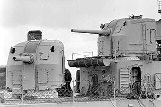
The Mark 12 5"/38-caliber gun was a United States dual-purpose naval gun, but also installed in single-purpose mounts on a handful of ships. The 38-caliber barrel was a mid-length compromise between the previous United States standard 5"/51 low-angle gun and 5"/25 anti-aircraft gun. United States naval gun terminology indicates the gun fired a projectile 5 inches (127 mm) in diameter, and the barrel was 38 calibers long. The increased barrel length provided greatly improved performance in both anti-aircraft and anti-surface roles compared to the 5"/25 gun. However, except for the barrel length and the use of semi-fixed ammunition, the 5"/38 gun was derived from the 5"/25 gun. Both weapons had power ramming, which enabled rapid fire at high angles against aircraft. The 5"/38 entered service on USS Farragut, commissioned in 1934, the first new destroyer design since the last Clemson was built in 1922. The base ring mount, which improved the effective rate of fire, entered service on USS Porter, commissioned in 1936.
A disappearing gun, a gun mounted on a disappearing carriage, is an obsolete type of artillery which enabled a gun to hide from direct fire and observation. The overwhelming majority of carriage designs enabled the gun to rotate backwards and down behind a parapet, or into a pit protected by a wall, after it was fired; a small number were simply barbette mounts on a retractable platform. Either way, retraction lowered the gun from view and direct fire by the enemy while it was being reloaded. It also made reloading easier, since it lowered the breech to a level just above the loading platform, and shells could be rolled right up to the open breech for loading and ramming. Other benefits over non-disappearing types were a higher rate of repetitive fire and less fatigue for the gun crew.
The 6-inch siege gun model 1877 was a Russian 152.4 mm (6 in) fortress gun, siege gun and coastal defense gun. It was used in the Russo-Japanese War, World War I, and the Russian Civil War. The successor states of the Russian Empire also inherited a number of M1877 guns.
The Iowa-class battleships are the most heavily armed warships the United States Navy has ever put to sea, due to the continual development of their onboard weaponry. The first Iowa-class ship was laid down in June 1940; in their World War II configuration, each of the Iowa-class battleships had a main battery of 16-inch (406 mm) guns that could hit targets nearly 20 statute miles (32 km) away with a variety of artillery shells designed for anti-ship or bombardment work. The secondary battery of 5-inch (127 mm) guns could hit targets nearly 9 statute miles (14 km) away with solid projectiles or proximity fuzed shells, and was effective in an anti-aircraft role as well. Each of the four battleships carried a wide array of 20 mm and 40 mm anti-aircraft guns for defense against enemy aircraft.
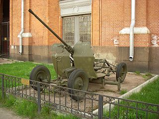
25 mm automatic air defense gun M1940 (72-K) was a Soviet 25 mm caliber anti-aircraft gun used during the World War II. The gun was developed from the end of 1939 to the beginning of 1940 at 8th Kalinin Artillery Plant under the guidance of its Chief Designer Mikhail Loginov, supervised by Lev Loktev. The cannon was given the factory code 72-K before being accepted into service by the Red Army as the 25 mm automatic air defense gun M1940.
The QF 3-inch 20 cwt anti-aircraft gun became the standard anti-aircraft gun used in the home defence of the United Kingdom against German Zeppelins airships and bombers and on the Western Front in World War I. It was also common on British warships in World War I and submarines in World War II. 20 cwt referred to the weight of the barrel and breech, to differentiate it from other 3-inch guns. While other AA guns also had a bore of 3 inches (76 mm), the term 3-inch was only ever used to identify this gun in the World War I era, and hence this is what writers are usually referring to by 3-inch AA gun.
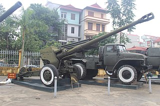
The 122mm D-74 towed gun is a Soviet field gun. Developed in the late 1940s, it served with the Soviet Army and was widely exported. A number were produced under license in the People's Republic of China as the Type 60.
The Canon de 75 antiaérien mle 1913–1917 were a family of French 75 mm anti-aircraft guns designed and manufactured by Schneider et Cie at Le Creusot. The guns were used by the French Army during the First World War and Second World War.
The Obusier de 370 modèle 1915 à berceau was a French Railroad Gun that saw action during the First World War and Second World War.
The 9 cm Kanone C/79 was a fortress and siege gun developed after the Franco-Prussian War and used by Germany before and during World War I.
References
Bellamy, Chris (1986). Red God of War – Soviet artillery and rocket forces. London: Brassey's Defence Publishers. ISBN0-08-031200-4.
Callwell, Charles; Headlam, John (1931). The History of the Royal Artillery – From the Indian Mutiny to the Great War. Vol.1 (1860–1899). Woolwich: Royal Artillery Institution.
Headlam, John (1934). The History of the Royal Artillery – From the Indian Mutiny to the Great War. Vol.2 (1899–1914). Woolwich: Royal Artillery Institution.
Hogg, OFG (1970). Artillery: Its origin, heyday and decline. London: C Hurst and Company.
The Official History of the Ministry of Munitions, Vol X The Supply of Munitions, Part VI Anti-Aircraft Supplies, 1922
This page is based on this Wikipedia article Text is available under the CC BY-SA 4.0 license; additional terms may apply. Images, videos and audio are available under their respective licenses.