H-bridge

Last updated

An H-bridge is an electronic circuit that switches the polarity of a voltage applied to a load. These circuits are often used in robotics and other applications to allow DC motors to run forwards or backwards. [1] The name is derived from its common schematic diagram representation, with four switching elements configured as the branches of a letter "H" and the load connected as the cross-bar.

Contents

Most DC-to-AC converters (power inverters), most AC/AC converters, the DC-to-DC push–pull converter, isolated DC-to-DC converter [2] most motor controllers, and many other kinds of power electronics use H bridges. In particular, a bipolar stepper motor is almost always driven by a motor controller containing two H bridges.

General

Schematic of an H-bridge (highlighted in red) H bridge.svg
Schematic of an H-bridge (highlighted in red)

H-bridges are available as integrated circuits, or can be built from discrete components. [1]

The term H-bridge is derived from the typical graphical representation of such a circuit. An H-bridge is built with four switches (solid-state or mechanical). When the switches S1 and S4 (according to the first figure) are closed (and S2 and S3 are open) a positive voltage is applied across the motor. By opening S1 and S4 switches and closing S2 and S3 switches, this voltage is reversed, allowing reverse operation of the motor.

Using the nomenclature above, the switches S1 and S2 should never be closed at the same time, as this would cause a short circuit on the input voltage source. The same applies to the switches S3 and S4. This condition is known as shoot-through.

Common usage

H bridge is used to supply power to a two terminal device. By proper arrangement of the switches, the polarity of the power to the device can be changed. Two examples are discussed below, DC motor Driver and transformer of switching regulator. Note that, not all of the case of switching condition is safe. The "short"(see below in "DC motor driver" section) cases are dangerous to the power source and to the switches.

DC motor Driver

The two basic states of an H bridge H bridge operating.svg
The two basic states of an H bridge

Changing the polarity of the power supply to DC motor is used to change the direction of rotation. Apart from changing the rotation direction, the H-bridge can provide additional operation modes, "brake" and "free run until frictional stop". The H-bridge arrangement is generally used to reverse the polarity/direction of the motor, but can also be used to 'brake' the motor, where the motor comes to a sudden stop when the motor's terminals are connected together. By connecting its terminals, the motor's kinetic energy is consumed rapidly in form of electrical current and causes the motor to slow down. Another case allows the motor to coast to a stop, as the motor is effectively disconnected from the circuit. The following table summarizes operation, with S1-S4 corresponding to the diagram above. In the table below, "1" is used to represent "on" state of the switch, "0" to represent the "off" state.

S1S2S3S4Result
1001Motor moves right
0110Motor moves left
0000Motor coasts
1000
0100
0010
0001
11XXShort circuit
XX11
1010Brakes
0101

Primary coil driver of switching power converter

Typical primary coil driver is to simply replace the two terminals of the DC motor by the two terminals of the primary coil. The switching current in the primary coil turns electrical energy into magnetic energy and transfers back to ac electrical energy in the secondary coil.

Construction

L298 dual H-bridge motor driver L298 IMGP4533 wp.jpg
L298 dual H-bridge motor driver

Relays

One way to build an H-bridge is to use an array of relays from a relay board. [3]

A "double pole double throw" (DPDT) relay can generally achieve the same electrical functionality as an H-bridge (considering the usual function of the device). However a semiconductor-based H-bridge would be preferable to the relay where a smaller physical size, high speed switching, or low driving voltage (or low driving power) is needed, or where the wearing out of mechanical parts is undesirable.

Another configuration is to have a DPDT relay to set the direction of current flow and a transistor to enable the current flow. This can extend the relay life, as the relay will be switched while the transistor is off and thereby there is no current flow. It also enables the use of PWM switching to control the current level.

N and P channel semiconductors

A solid-state H-bridge is typically constructed using opposite polarity devices, such as PNP bipolar junction transistors (BJT) or P-channel MOSFETs connected to the high voltage bus and NPN BJTs or N-channel MOSFETs connected to the low voltage bus.

N channel-only semiconductors

The most efficient MOSFET designs use N-channel MOSFETs on both the high side and low side because they typically have a third of the ON resistance of P-channel MOSFETs. This requires a more complex design since the gates of the high side MOSFETs must be driven positive with respect to the DC supply rail. Many integrated circuit MOSFET gate drivers include a charge pump within the device to achieve this.

Alternatively, a switched-mode power supply DC–DC converter can be used to provide isolated ('floating') supplies to the gate drive circuitry. A multiple-output flyback converter is well-suited to this application.

Another method for driving MOSFET-bridges is the use of a specialised transformer known as a GDT (gate drive transformer), which gives the isolated outputs for driving the upper FETs gates. The transformer core is usually a ferrite toroid, with 1:1 or 4:9 winding ratio. However, this method can only be used with high frequency signals. The design of the transformer is also very important, as the leakage inductance should be minimized, or cross conduction may occur. The outputs of the transformer are usually clamped by Zener diodes, because high voltage spikes could destroy the MOSFET gates.

Variants

A common variation of this circuit uses just the two transistors on one side of the load, similar to a class AB amplifier. Such a configuration is called a "half bridge". [4] It acts as an electronic toggle switch, the half bridge is not able to switch polarity of the voltage applied to the load. The half bridge is used in some switched-mode power supplies that use synchronous rectifiers and in switching amplifiers. The half-H bridge type is commonly abbreviated to "Half-H" to distinguish it from full ("Full-H") H-bridges. Another common variation, adding a third 'leg' to the bridge, creates a three-phase inverter. The three-phase inverter is the core of any AC motor drive.

A further variation is the half-controlled bridge, where the low-side switching device on one side of the bridge, and the high-side switching device on the opposite side of the bridge, are each replaced with diodes. This eliminates the shoot-through failure mode, and is commonly used to drive variable or switched reluctance machines and actuators where bi-directional current flow is not required.

Commercial availability

There are many commercially available inexpensive single and dual H-bridge packages. The L293x series, being technically mostly obsolete since the late 1970s due to decreased switching losses and higher speeds in more modern semiconductor products, is still found in many hobbyist circuitry. Few packages, like L9110, [5] have built-in flyback diodes for back EMF protection.

Operation as an inverter

A common use of the H-bridge is an inverter. The arrangement is sometimes known as a single-phase bridge inverter.

The H-bridge with a DC supply will generate a square wave voltage waveform across the load. For a purely inductive load, the current waveform would be a triangle wave, with its peak depending on the inductance, switching frequency, and input voltage.

See also

Related Research Articles

<span class="mw-page-title-main">Amplifier</span> Electronic device/component that increases the strength of a signal

An amplifier, electronic amplifier or (informally) amp is an electronic device that can increase the magnitude of a signal. It is a two-port electronic circuit that uses electric power from a power supply to increase the amplitude of a signal applied to its input terminals, producing a proportionally greater amplitude signal at its output. The amount of amplification provided by an amplifier is measured by its gain: the ratio of output voltage, current, or power to input. An amplifier is defined as a circuit that has a power gain greater than one.

<span class="mw-page-title-main">Rectifier</span> Electrical device that converts AC to DC

A rectifier is an electrical device that converts alternating current (AC), which periodically reverses direction, to direct current (DC), which flows in only one direction. The reverse operation is performed by an inverter.

<span class="mw-page-title-main">Thyristor</span> Type of solid state switch

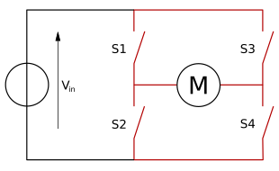
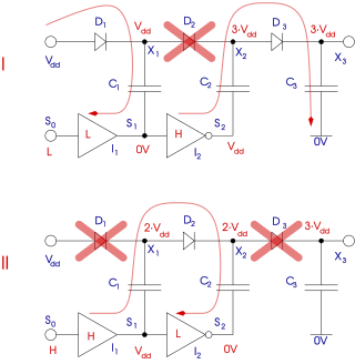
A thyristor is a solid-state semiconductor device which can be thought of as being a highly robust and switchable diode, allowing the passage of current in one direction but not the other, often under control of a gate electrode, that is used in high power applications like inverters and radar generators. It usually consists of four layers of alternating P- and N-type materials. It acts as a bistable switch. There are two designs, differing in what triggers the conducting state. In a three-lead thyristor, a small current on its gate lead controls the larger current of the anode-to-cathode path. In a two-lead thyristor, conduction begins when the potential difference between the anode and cathode themselves is sufficiently large. The thyristor continues conducting until the voltage across the device is reverse-biased or the voltage is removed, or through the control gate signal on newer types.

<span class="mw-page-title-main">Power inverter</span> Device that changes direct current (DC) to alternating current (AC)

A power inverter, inverter, or invertor is a power electronic device or circuitry that changes direct current (DC) to alternating current (AC). The resulting AC frequency obtained depends on the particular device employed. Inverters do the opposite of rectifiers which were originally large electromechanical devices converting AC to DC.

<span class="mw-page-title-main">Switched-mode power supply</span> Power supply with switching regulator

A switched-mode power supply (SMPS), also called switching-mode power supply, switch-mode power supply, switched power supply, or simply switcher, is an electronic power supply that incorporates a switching regulator to convert electrical power efficiently.

A DC-to-DC converter is an electronic circuit or electromechanical device that converts a source of direct current (DC) from one voltage level to another. It is a type of electric power converter. Power levels range from very low to very high.

<span class="mw-page-title-main">Voltage regulator</span> System designed to maintain a constant voltage

A voltage regulator is a system designed to automatically maintain a constant voltage. It may use a simple feed-forward design or may include negative feedback. It may use an electromechanical mechanism, or electronic components. Depending on the design, it may be used to regulate one or more AC or DC voltages.

<span class="mw-page-title-main">Power electronics</span> Technology of power electronics

Power electronics is the application of electronics to the control and conversion of electric power.

A voltage doubler is an electronic circuit which charges capacitors from the input voltage and switches these charges in such a way that, in the ideal case, exactly twice the voltage is produced at the output as at its input.

<span class="mw-page-title-main">Charge pump</span> Electric converter

A charge pump is a kind of DC-to-DC converter that uses capacitors for energetic charge storage to raise or lower voltage. Charge-pump circuits are capable of high efficiencies, sometimes as high as 90–95%, while being electrically simple circuits.

This is an alphabetical list of articles pertaining specifically to electrical and electronics engineering. For a thematic list, please see List of electrical engineering topics. For a broad overview of engineering, see List of engineering topics. For biographies, see List of engineers.

<span class="mw-page-title-main">Buck converter</span> DC-DC voltage step-down power converter

A buck converter or step-down converter is a DC-to-DC converter which decreases voltage, while increasing current, from its input (supply) to its output (load). It is a class of switched-mode power supply. Switching converters provide much greater power efficiency as DC-to-DC converters than linear regulators, which are simpler circuits that dissipate power as heat, but do not step up output current. The efficiency of buck converters can be very high, often over 90%, making them useful for tasks such as converting a computer's main supply voltage, which is usually 12 V, down to lower voltages needed by USB, DRAM and the CPU, which are usually 5, 3.3 or 1.8 V.

<span class="mw-page-title-main">Push–pull converter</span>

A push–pull converter is a type of DC-to-DC converter, a switching converter that uses a transformer to change the voltage of a DC power supply. The distinguishing feature of a push-pull converter is that the transformer primary is supplied with current from the input line by pairs of transistors in a symmetrical push-pull circuit. The transistors are alternately switched on and off, periodically reversing the current in the transformer. Therefore, current is drawn from the line during both halves of the switching cycle. This contrasts with buck-boost converters, in which the input current is supplied by a single transistor which is switched on and off, so current is drawn from the line during only a part of the switching cycle. During the remainder of the cycle, the output power is supplied by energy stored in inductors or capacitors in the power supply. Push–pull converters have steadier input current, create less noise on the input line, and are more efficient in higher power applications.

<span class="mw-page-title-main">Single-ended primary-inductor converter</span> Electrical device

The single-ended primary-inductor converter (SEPIC) is a type of DC/DC converter that allows the electrical potential (voltage) at its output to be greater than, less than, or equal to that at its input. The output of the SEPIC is controlled by the duty cycle of the control switch (S1).

<span class="mw-page-title-main">Flyback diode</span> Voltage-spike stopping diode across an inductor

A flyback diode is any diode connected across an inductor used to eliminate flyback, which is the sudden voltage spike seen across an inductive load when its supply current is suddenly reduced or interrupted. It is used in circuits in which inductive loads are controlled by switches, and in switching power supplies and inverters.

A Royer oscillator is an electronic relaxation oscillator that employs a saturable-core transformer in the main power path. It was invented and patented in April 1954 by Richard L. Bright & George H. Royer, who are listed as co-inventors on the patent. It has the advantages of simplicity, low component count, rectangle waveforms, and transformer isolation. As well as being an inverter, it can be used as a galvanically-isolated DC-DC converter when the transformer output winding is connected to a suitable rectifying stage, in which case the resulting apparatus is usually called a "Royer Converter".

A gate driver is a power amplifier that accepts a low-power input from a controller IC and produces a high-current drive input for the gate of a high-power transistor such as an IGBT or power MOSFET. Gate drivers can be provided either on-chip or as a discrete module. In essence, a gate driver consists of a level shifter in combination with an amplifier. A gate driver IC serves as the interface between control signals and power switches. An integrated gate-driver solution reduces design complexity, development time, bill of materials (BOM), and board space while improving reliability over discretely-implemented gate-drive solutions.

The following outline is provided as an overview of and topical guide to electronics:

This glossary of electrical and electronics engineering is a list of definitions of terms and concepts related specifically to electrical engineering and electronics engineering. For terms related to engineering in general, see Glossary of engineering.

References

  1. 1 2 Al Williams (2002). Microcontroller projects using the Basic Stamp (2nd ed.). Focal Press. p. 344. ISBN   978-1-57820-101-3.
  2. "11kW, 70kHz LLC Converter Design for 98% Efficiency". November 2020: 1–8. doi:10.1109/COMPEL49091.2020.9265771. S2CID   227278364.{{cite journal}}: Cite journal requires |journal= (help)
  3. "Relay H-bridge (Relay Motor controller)". 11 December 2012.
  4. ""H-Bridges"".
  5. "wordpress.com" (PDF).

Projects