In physics, the Coriolis force is an inertial or fictitious force that acts on objects in motion within a frame of reference that rotates with respect to an inertial frame. In a reference frame with clockwise rotation, the force acts to the left of the motion of the object. In one with anticlockwise rotation, the force acts to the right. Deflection of an object due to the Coriolis force is called the Coriolis effect. Though recognized previously by others, the mathematical expression for the Coriolis force appeared in an 1835 paper by French scientist Gaspard-Gustave de Coriolis, in connection with the theory of water wheels. Early in the 20th century, the term Coriolis force began to be used in connection with meteorology.

A sextant is a doubly reflecting navigation instrument that measures the angular distance between two visible objects. The primary use of a sextant is to measure the angle between an astronomical object and the horizon for the purposes of celestial navigation.

The horizon is the apparent curve that separates the surface of a celestial body from its sky when viewed from the perspective of an observer on or near the surface of the relevant body. This curve divides all viewing directions based on whether it intersects the relevant body's surface or not.

A sundial is a horological device that tells the time of day when direct sunlight shines by the apparent position of the Sun in the sky. In the narrowest sense of the word, it consists of a flat plate and a gnomon, which casts a shadow onto the dial. As the Sun appears to move through the sky, the shadow aligns with different hour-lines, which are marked on the dial to indicate the time of day. The style is the time-telling edge of the gnomon, though a single point or nodus may be used. The gnomon casts a broad shadow; the shadow of the style shows the time. The gnomon may be a rod, wire, or elaborately decorated metal casting. The style must be parallel to the axis of the Earth's rotation for the sundial to be accurate throughout the year. The style's angle from horizontal is equal to the sundial's geographical latitude.

A trajectory or flight path is the path that an object with mass in motion follows through space as a function of time. In classical mechanics, a trajectory is defined by Hamiltonian mechanics via canonical coordinates; hence, a complete trajectory is defined by position and momentum, simultaneously.

An alidade or a turning board is a device that allows one to sight a distant object and use the line of sight to perform a task. This task can be, for example, to triangulate a scale map on site using a plane table drawing of intersecting lines in the direction of the object from two or more points or to measure the angle and horizontal distance to the object from some reference point's polar measurement. Angles measured can be horizontal, vertical or in any chosen plane.

Magnification is the process of enlarging the apparent size, not physical size, of something. This enlargement is quantified by a size ratio called optical magnification. When this number is less than one, it refers to a reduction in size, sometimes called de-magnification.
Projectile motion is a form of motion experienced by an object or particle that is projected in a gravitational field, such as from Earth's surface, and moves along a curved path under the action of gravity only. In the particular case of projectile motion on Earth, most calculations assume the effects of air resistance are passive and negligible. The curved path of objects in projectile motion was shown by Galileo to be a parabola, but may also be a straight line in the special case when it is thrown directly upward or downward. The study of such motions is called ballistics, and such a trajectory is a ballistic trajectory. The only force of mathematical significance that is actively exerted on the object is gravity, which acts downward, thus imparting to the object a downward acceleration towards the Earth’s center of mass. Because of the object's inertia, no external force is needed to maintain the horizontal velocity component of the object's motion. Taking other forces into account, such as aerodynamic drag or internal propulsion, requires additional analysis. A ballistic missile is a missile only guided during the relatively brief initial powered phase of flight, and whose remaining course is governed by the laws of classical mechanics.
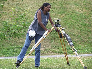
Levelling or leveling is a branch of surveying, the object of which is to establish or verify or measure the height of specified points relative to a datum. It is widely used in geodesy and cartography to measure vertical position with respect to a vertical datum, and in construction to measure height differences of construction artifacts.
The Scheimpflug principle is a description of the geometric relationship between the orientation of the plane of focus, the lens plane, and the image plane of an optical system when the lens plane is not parallel to the image plane. It is applicable to the use of some camera movements on a view camera. It is also the principle used in corneal pachymetry, the mapping of corneal topography, done prior to refractive eye surgery such as LASIK, and used for early detection of keratoconus. The principle is named after Austrian army Captain Theodor Scheimpflug, who used it in devising a systematic method and apparatus for correcting perspective distortion in aerial photographs, although Captain Scheimpflug himself credits Jules Carpentier with the rule, thus making it an example of Stigler's law of eponymy.

Atmospheric refraction is the deviation of light or other electromagnetic wave from a straight line as it passes through the atmosphere due to the variation in air density as a function of height. This refraction is due to the velocity of light through air decreasing with increased density. Atmospheric refraction near the ground produces mirages. Such refraction can also raise or lower, or stretch or shorten, the images of distant objects without involving mirages. Turbulent air can make distant objects appear to twinkle or shimmer. The term also applies to the refraction of sound. Atmospheric refraction is considered in measuring the position of both celestial and terrestrial objects.

Stadiametric rangefinding, or the stadia method, is a technique of measuring distances with a telescopic instrument. The term stadia comes from a Greek unit of length Stadion which was the typical length of a sports stadium of the time. Stadiametric rangefinding is used for surveying and in the telescopic sights of firearms, artillery pieces, or tank guns, as well as some binoculars and other optics. It is still widely used in long-range military sniping, but in many professional applications it is being replaced with microwave, infrared, or laser rangefinding methods. Although much easier to use, electronic rangefinders can give away the shooter's position to a well-equipped adversary, and the need for accurate range estimation existed for much longer than electronic rangefinders small and rugged enough to be suitable for military use.
In astronomical navigation, the intercept method, also known as Marcq St. Hilaire method, is a method of calculating an observer's position on Earth (geopositioning). It was originally called the azimuth intercept method because the process involves drawing a line which intercepts the azimuth line. This name was shortened to intercept method and the intercept distance was shortened to 'intercept'.

A spacetime diagram is a graphical illustration of objects' locations in space at various times, especially in the special theory of relativity. Spacetime diagrams can show the geometry underlying phenomena like time dilation and length contraction without mathematical equations.

In technical drawing and computer graphics, a multiview projection is a technique of illustration by which a standardized series of orthographic two-dimensional pictures are constructed to represent the form of a three-dimensional object. Up to six pictures of an object are produced, with each projection plane parallel to one of the coordinate axes of the object. The views are positioned relative to each other according to either of two schemes: first-angle or third-angle projection. In each, the appearances of views may be thought of as being projected onto planes that form a six-sided box around the object. Although six different sides can be drawn, usually three views of a drawing give enough information to make a three-dimensional object. These views are known as front view, top view and end view. Other names for these views include plan, elevation and section. When the plane or axis of the object depicted is not parallel to the projection plane, and where multiple sides of an object are visible in the same image, it is called an auxiliary view.

The geometric design of roads is the branch of highway engineering concerned with the positioning of the physical elements of the roadway according to standards and constraints. The basic objectives in geometric design are to optimize efficiency and safety while minimizing cost and environmental damage. Geometric design also affects an emerging fifth objective called "livability," which is defined as designing roads to foster broader community goals, including providing access to employment, schools, businesses and residences, accommodate a range of travel modes such as walking, bicycling, transit, and automobiles, and minimizing fuel use, emissions and environmental damage.
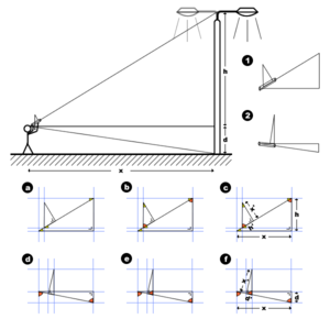
In trigonometry, a skinny triangle is a triangle whose height is much greater than its base. The solution of such triangles can be greatly simplified by using the approximation that the sine of a small angle is equal to that angle in radians. The solution is particularly simple for skinny triangles that are also isosceles or right triangles: in these cases the need for trigonometric functions or tables can be entirely dispensed with.
Tree height is the vertical distance between the base of the tree and the tip of the highest branch on the tree, and is difficult to measure accurately. It is not the same as the length of the trunk. If a tree is leaning, the trunk length may be greater than the height of the tree. The base of the tree is where the projection of the pith (center) of the tree intersects the existing supporting surface upon which the tree is growing or where the seed sprouted. If the tree is growing on the side of a cliff, the base of the tree is at the point where the pith would intersect the cliff side. Roots extending down from that point would not add to the height of the tree. On a slope this base point is considered as halfway between the ground level at the upper and lower sides of the tree. Tree height can be measured in a number of ways with varying degrees of accuracy.
A schema for horizontal dials is a set of instructions used to construct horizontal sundials using compass and straightedge construction techniques, which were widely used in Europe from the late fifteenth century to the late nineteenth century. The common horizontal sundial is a geometric projection of an equatorial sundial onto a horizontal plane.

Vertical declining dials are sundials that indicate local apparent time. Vertical south dials are a special case: as are vertical north, vertical east and vertical west dials. The word declining means that the wall is offset from one of these 4 cardinal points. There are dials that are not vertical, and these are called reclining dials.