
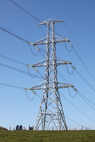
Three-phase electric power is a common type of alternating current (AC) used in electricity generation, transmission, and distribution. It is a type of polyphase system employing three wires and is the most common method used by electrical grids worldwide to transfer power.
In electrical engineering, the power factor of an AC power system is defined as the ratio of the real power absorbed by the load to the apparent power flowing in the circuit. Real power is the average of the instantaneous product of voltage and current and represents the capacity of the electricity for performing work. Apparent power is the product of RMS current and voltage. Due to energy stored in the load and returned to the source, or due to a non-linear load that distorts the wave shape of the current drawn from the source, the apparent power may be greater than the real power, so more current flows in the circuit than would be required to transfer real power alone. A power factor magnitude of less than one indicates the voltage and current are not in phase, reducing the average product of the two. A negative power factor occurs when the device generates real power, which then flows back towards the source.
The propagation constant of a sinusoidal electromagnetic wave is a measure of the change undergone by the amplitude and phase of the wave as it propagates in a given direction. The quantity being measured can be the voltage, the current in a circuit, or a field vector such as electric field strength or flux density. The propagation constant itself measures the change per unit length, but it is otherwise dimensionless. In the context of two-port networks and their cascades, propagation constant measures the change undergone by the source quantity as it propagates from one port to the next.

In electrical engineering, impedance is the opposition to alternating current presented by the combined effect of resistance and reactance in a circuit.

Astronomicalcoordinate systems are organized arrangements for specifying positions of satellites, planets, stars, galaxies, and other celestial objects relative to physical reference points available to a situated observer. Coordinate systems in astronomy can specify an object's position in three-dimensional space or plot merely its direction on a celestial sphere, if the object's distance is unknown or trivial.
In linear algebra, an invertible complex square matrix U is unitary if its conjugate transpose U* is also its inverse, that is, if
In electromagnetics, an evanescent field, or evanescent wave, is an oscillating electric and/or magnetic field that does not propagate as an electromagnetic wave but whose energy is spatially concentrated in the vicinity of the source. Even when there is a propagating electromagnetic wave produced, one can still identify as an evanescent field the component of the electric or magnetic field that cannot be attributed to the propagating wave observed at a distance of many wavelengths.

In astronomy, superluminal motion is the apparently faster-than-light motion seen in some radio galaxies, BL Lac objects, quasars, blazars and recently also in some galactic sources called microquasars. Bursts of energy moving out along the relativistic jets emitted from these objects can have a proper motion that appears greater than the speed of light. All of these sources are thought to contain a black hole, responsible for the ejection of mass at high velocities. Light echoes can also produce apparent superluminal motion.
In power engineering, the power-flow study, or load-flow study, is a numerical analysis of the flow of electric power in an interconnected system. A power-flow study usually uses simplified notations such as a one-line diagram and per-unit system, and focuses on various aspects of AC power parameters, such as voltages, voltage angles, real power and reactive power. It analyzes the power systems in normal steady-state operation.
The classical XY model is a lattice model of statistical mechanics. In general, the XY model can be seen as a specialization of Stanley's n-vector model for n = 2.
In the Standard Model of particle physics, the Cabibbo–Kobayashi–Maskawa matrix, CKM matrix, quark mixing matrix, or KM matrix is a unitary matrix which contains information on the strength of the flavour-changing weak interaction. Technically, it specifies the mismatch of quantum states of quarks when they propagate freely and when they take part in the weak interactions. It is important in the understanding of CP violation. This matrix was introduced for three generations of quarks by Makoto Kobayashi and Toshihide Maskawa, adding one generation to the matrix previously introduced by Nicola Cabibbo. This matrix is also an extension of the GIM mechanism, which only includes two of the three current families of quarks.

In electrical engineering, three-phase electric power systems have at least three conductors carrying alternating voltages that are offset in time by one-third of the period. A three-phase system may be arranged in delta (∆) or star (Y). A wye system allows the use of two different voltages from all three phases, such as a 230/400 V system which provides 230 V between the neutral and any one of the phases, and 400 V across any two phases. A delta system arrangement provides only one voltage, but it has a greater redundancy as it may continue to operate normally with one of the three supply windings offline, albeit at 57.7% of total capacity. Harmonic current in the neutral may become very large if nonlinear loads are connected.
In rotordynamics, the rigid rotor is a mechanical model of rotating systems. An arbitrary rigid rotor is a 3-dimensional rigid object, such as a top. To orient such an object in space requires three angles, known as Euler angles. A special rigid rotor is the linear rotor requiring only two angles to describe, for example of a diatomic molecule. More general molecules are 3-dimensional, such as water, ammonia, or methane.

In physics and engineering, a phasor is a complex number representing a sinusoidal function whose amplitude, angular frequency, and initial phase are time-invariant. It is related to a more general concept called analytic representation, which decomposes a sinusoid into the product of a complex constant and a factor depending on time and frequency. The complex constant, which depends on amplitude and phase, is known as a phasor, or complex amplitude, and sinor or even complexor.
Electric power is the rate at which electrical energy is transferred by an electric circuit. The SI unit of power is the watt, one joule per second. Standard prefixes apply to watts as with other SI units: thousands, millions and billions of watts are called kilowatts, megawatts and gigawatts respectively.

The differentiation of trigonometric functions is the mathematical process of finding the derivative of a trigonometric function, or its rate of change with respect to a variable. For example, the derivative of the sine function is written sin′(a) = cos(a), meaning that the rate of change of sin(x) at a particular angle x = a is given by the cosine of that angle.
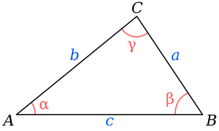
In trigonometry, the law of cosines relates the lengths of the sides of a triangle to the cosine of one of its angles. For a triangle with sides and opposite respective angles and , the law of cosines states:
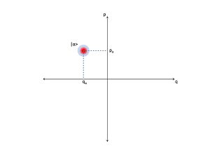
In quantum optics, an optical phase space is a phase space in which all quantum states of an optical system are described. Each point in the optical phase space corresponds to a unique state of an optical system. For any such system, a plot of the quadratures against each other, possibly as functions of time, is called a phase diagram. If the quadratures are functions of time then the optical phase diagram can show the evolution of a quantum optical system with time.
In electrical engineering, the alpha-betatransformation is a mathematical transformation employed to simplify the analysis of three-phase circuits. Conceptually it is similar to the dq0 transformation. One very useful application of the transformation is the generation of the reference signal used for space vector modulation control of three-phase inverters.


