MIPI Debug Architecture

Last updated

MIPI Alliance Debug Architecture provides a standardized infrastructure for debugging deeply embedded systems in the mobile and mobile-influenced space. The MIPI Alliance MIPI Debug Working Group has released a portfolio of specifications; their objective is to provide standard debug protocols and standard interfaces from a system on a chip (SoC) to the debug tool. The whitepaper Architecture Overview for Debug summarizes all the efforts. In recent years, the group focused on specifying protocols that improve the visibility of the internal operations of deeply embedded systems, standardizing debug solutions via the functional interfaces of form factor devices, and specifying the use of I3C as debugging bus. [1] [2]

Contents

The term "debug"

The term "debug" encompasses the various methods used to detect, triage, trace, and potentially eliminate mistakes, or bugs, in hardware and software. Debug includes control/configure methods, stop/step mode debugging, and various forms of tracing.

Control/configure methods

Debug can be used to control and configure components, including embedded systems, of a given target system. Standard functions include setting up hardware breakpoints, preparing and configuring the trace system, and examining system states.

Stop/step mode debugging

In stop/step mode debugging, the core/microcontroller is stopped through the use of breakpoints and then "single-stepped" through the code by executing instructions one at a time. If the other cores/microcontrollers of the SoC have finished synchronously, the overall state of the system can be examined. Stop/step mode debugging includes control/configure techniques, run control of a core/microcontroller, start/stop synchronization with other cores, memory and register access, and additional debug features such as performance counter and run-time memory access.

Tracing

Traces allow an in-depth analysis of the behavior and the timing characteristics of an embedded system. The following traces are typical:

Visibility of SoC-internal operations

Layering of the trace specifications Mipi trace-topology.png
Layering of the trace specifications

Tracing is the tool of choice to monitor and analyze what is going on in a complex SoC. There are several well established non-MIPI core-trace and bus-trace standards for the embedded market. Thus, there was no need for the MIPI Debug Working Group to specify new ones. But no standard existed for a "system trace" when the Debug Working Group published its first version of the MIPI System Trace Protocol (MIPI STP) in 2006.

MIPI System Software Trace (MIPI SyS-T)

The generation of system trace data from the software is typically done by inserting additional function calls, which produce diagnostic information valuable for the debug process. This debug technique is called instrumentation. Examples are: printf-style string generating functions, value information, assertions, etc. The purpose of MIPI System Software Trace (MIPI SyS-T) is to define a reusable, general-purpose data protocol and instrumentation API for debugging. The specification defines message formats that allow a trace-analysis tool to decode the debug messages, either into human-readable text or to signals optimized for automated analysis.

Since verbose textual messages stress bandwidth limits for debugging, so-called "catalog messages" are provided. Catalog messages are compact binary messages that replace strings with numeric values. The translation from the numeric value to a message string is done by the trace analysis tool, with the help of collateral XML information. This information is provided during the software-build process using an XML schema that is part of the specification as well.

The SyS-T data protocol is designed to work efficiently on top of lower-level transport links such as those defined by the MIPI System Trace Protocol. SyS-T protocol features such as timestamping or data-integrity checksums can be disabled if the transport link already provides such capabilities. The use of other transport links—such as UART, USB, or TCP/IP—is also possible.

The MIPI Debug Working Group will provide an open-source reference implementation for the SyS-T instrumentation API, a SyS-T message pretty printer, and a tool to generate the XML collateral data as soon as the Specification for System Software Trace (SyS-T) is approved. [3]

MIPI System Trace Protocol (MIPI STP)

Master/channel topology of System Trace Module Stm master channel.png
Master/channel topology of System Trace Module

The MIPI System Trace Protocol (MIPI STP) specifies a generic protocol that allows the merging of trace streams originated from anywhere in the SoC to a trace stream of 4-bit frames. It was intentionally designed to merge system trace information. The MIPI System Trace Protocol uses a channel/master topology that allows the trace receiving analysis tool to collate the individual trace streams for analysis and display. The protocol additionally provides the following features: stream synchronization and alignment, trigger markers, global timestamping, and multiple stream time synchronization.

The stream of STP packets produced by the System Trace Module can be directly saved to trace RAM, directly exported off-chip, or can be routed to a trace wrapper protocol (TWP) module to merge with further trace streams. ARM's CoreSight System Trace Macrocell, [4] which is compliant with MIPI STP, is today an integral part of most multi-core chips used in the mobile space.

The last MIPI board-adopted version of Specification for System Trace Protocol (STPSM) is version 2.2 (February 2016). [5]

MIPI Trace Wrapper Protocol (MIPI TWP)

The MIPI Trace Wrapper Protocol enables multiple trace streams to be merged into a single trace stream (byte streams). A unique ID is assigned to each trace stream by a wrapping protocol. The detection of byte/word boundaries is possible even if the data is transmitted as a stream of bits. Inert packets are used if a continuous export of trace data is required. MIPI Trace Wrapper Protocol is based on ARM's Trace Formatter Protocol specified for ARM CoreSight.

The last MIPI board-adopted version of Specification for Trace Wrapper Protocol (TWPSM) is version 1.1 (December 2014). [6]

From dedicated to functional interfaces

From dedicated to functional interfaces DedicatedToFunctional.png
From dedicated to functional interfaces

Dedicated debug interfaces

The two most common stop mode debugging technologies StopModeDebugging.png
The two most common stop mode debugging technologies

In the early stages of product development, it is common to use development boards with dedicated and readily accessible debug interfaces for connecting the debug tools. SoCs employed in the mobile market rely on two debug technologies: stop-mode debugging via a scan chain and stop-mode debugging via memory-mapped debug registers.

The following non-MIPI debug standards are well established in the embedded market: IEEE 1149.1 JTAG (5-pin) and ARM Serial Wire Debug (2-pin), both using single-ended pins. Thus, there was no need for the MIPI Debug Working Group to specify a stop-mode debug protocol or to specify a debug interface.

Trace data generated and merged to a trace stream within the SoC can be streamed, via a dedicated unidirectional trace interface, off-chip to a trace analysis tool. The MIPI Debug Architecture provides specifications for both parallel and serial trace ports.

The MIPI Parallel Trace Interface (MIPI PTI) specifies how to pass the trace data to multiple data pins and a clock pin (single-ended). The specification includes signal names and functions, timing, and electrical constraints. The last MIPI board-adopted version of Specification for Parallel Trace Interface is version 2.0 (October 2011). [7]

The MIPI High-Speed Trace Interface (MIPI HTI) specifies how to stream trace data over the physical layer of standard interfaces, such as PCI Express, DisplayPort, HDMI, or USB. The current version of the specification allows for one to six lanes. The specification includes:

34-pin board level connector Mipi34.svg
34-pin board level connector

The HTI is a subset of the High Speed Serial Trace Port (HSSTP) specification defined by ARM. [8] The last MIPI board-adopted version of Specification for High-speed Trace Interface is version 1.0 (July 2016). [9]

Board developers and debug tool vendors benefit from standard debug connectors and standard pin mappings. The MIPI Recommendation for Debug and Trace Connectors recommends 10-/20-/34-pin board-level 1.27-millimetre (0.050 in) connectors (MIPI10/20/34). Seven different pin mappings that address a wide variety of debug scenarios have been specified. They include standard JTAG (IEEE 1149.1), cJTAG (IEEE 1149.7) and 4-bit parallel trace interfaces (mainly used for system traces), supplemented by the ARM-specific Serial Wire Debug (SWD) standard. [10] MIPI10/20/34 debug connectors became the standard for ARM-based embedded designs.

Many embedded designs in the mobile space use high-speed parallel trace ports (up to 600 megabits per second per pin). MIPI recommends a 60-pin Samtec QSH/QTH connector named MIPI60, which allows JTAG/cJTAG for run control, up to 40 trace data signals, and up to 4 trace clocks. To minimize complexity, the recommendation defines four standard configurations with one, two, three, or four trace channels of varying width.

The last MIPI board-adopted version of MIPI Alliance Recommendation for Debug and Trace Connectors is version 1.1 (March 2011). [11]

PHY and pin overlaid interfaces

USB Type-C, USB2 pins used for SWD debug Typec map.png
USB Type-C, USB2 pins used for SWD debug
USB Type-C multiplexer switches USB2 pins to SWD pins Typec mux.png
USB Type-C multiplexer switches USB2 pins to SWD pins

Readily-accessible debug interfaces are not available in the product's final form factor. This hampers the identification of bugs and performance optimization in the end product. Since the debug logic is still present in the end product, an alternative access path is needed. An effective way is to equip a mobile terminal's standard interface with a multiplexer that allows for accessing the debug logic. The switching between the interface's essential function and the debug function can be initiated by the connected debug tool or by the mobile terminal's software. Standard debug tools can be used under the following conditions:

The MIPI Narrow Interface for Debug and Test (MIPI NIDnT) covers debugging via the following standard interfaces: microSD, USB 2.0 Micro-B/-AB receptacle, USB Type-C receptacle, and DisplayPort. The last MIPI board-adopted version of Specification for Narrow Interface for Debug and Test (NIDnTSM) is version 1.2 (December 2017). [12]

Network interfaces

MIPI SneakPeek Protocol (MIPI SPP) SneakpeekProtocol.png
MIPI SneakPeek Protocol (MIPI SPP)

Instead of re-using the pins, debugging can also be done via the protocol stack of a standard interface or network. Here debug traffic co-exists with the traffic of other applications using the same communication link. The MIPI Debug Working Group named this approach GigaBit Debug. Since no debug protocol existed for this approach, the MIPI Debug Working Group specified its SneakPeak debug protocol.

MIPI SneakPeek Protocol (MIPI SPP) moved from a dedicated interface for basic debugging towards a protocol-driven interface:

The MIPI Alliance Specification for SneakPeek Protocol describes the basic concepts, the required infrastructure, the packets, and the data flow. The last MIPI board-adopted version of Specification for SneakPeek Protocol (SPPSM) is version 1.0 (August 2015). [13]

The MIPI Gigabit Debug Specification Family is providing details for mapping debug and trace protocols to standard I/Os or networks available in mobile terminals. These details include: endpoint addressing, link initialization and management, data packaging, data-flow management, and error detection and recovery. The last MIPI board-adopted version of Specification for Gigabit Debug for USB (MIPI GbD USB) is version 1.1 (March 2018). [14] The last MIPI board-adopted version of Specification for Gigabit Debug for Internet Protocol Sockets (MIPI GbD IPS) is version 1.0 (July 2016). [15]

I3C as debug bus

Current debug solutions, such as JTAG and ARM CoreSight, are statically structured, which makes for limited scalability regarding the accessibility of debug components/devices. MIPI Debug for I3C specifies a scalable, 2-pin, single-ended debug solution, which has the advantage of being available for the entire product lifetime. The I3C bus can be used as a debug bus only, or the bus can be shared between debug and its essential function as data acquisition bus for sensors. Debugging via I3C works in principle as follows:

Related Research Articles

<span class="mw-page-title-main">USB</span> Standard for computer data connections

Universal Serial Bus (USB) is an industry standard that allows data exchange and delivery of power between many various types of electronics. It specifies its architecture, in particular its the physical interface, and communication protocols for data transfer and power delivery to and from hosts, such as personal computers, to and from peripheral devices, e.g. displays, keyboards, and mass storage devices, and to and from intermediate hubs, which multiply the number of a host's ports. USB was originally designed to standardize the connection of peripherals to computers, replacing various interfaces such as serial ports, parallel ports, game ports, and ADB ports, and prior versions of USB became commonplace on a wide range of devices, such as keyboards, mice, cameras, printers, scanners, flash drives, smartphones, game consoles, and power banks. It has evolved into a standard to replace virtually all common ports on computers, mobile devices, peripherals, power supplies, and manifold other small electronics. In the current standard the USB-C connector replaces the many various connectors for power, displays, and many other uses, as well as all previous USB connectors.

<span class="mw-page-title-main">Debugger</span> Computer program used to test and debug other programs

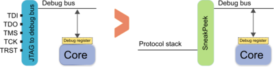
A debugger or debugging tool is a computer program used to test and debug other programs. The main use of a debugger is to run the target program under controlled conditions that permit the programmer to track its execution and monitor changes in computer resources that may indicate malfunctioning code. Typical debugging facilities include the ability to run or halt the target program at specific points, display the contents of memory, CPU registers or storage devices, and modify memory or register contents in order to enter selected test data that might be a cause of faulty program execution.

<span class="mw-page-title-main">AVR microcontrollers</span> Family of microcontrollers

AVR is a family of microcontrollers developed since 1996 by Atmel, acquired by Microchip Technology in 2016. These are modified Harvard architecture 8-bit RISC single-chip microcontrollers. AVR was one of the first microcontroller families to use on-chip flash memory for program storage, as opposed to one-time programmable ROM, EPROM, or EEPROM used by other microcontrollers at the time.

<span class="mw-page-title-main">PCI Express</span> Computer expansion bus standard

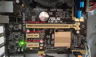
PCI Express, officially abbreviated as PCIe or PCI-e, is a high-speed serial computer expansion bus standard, designed to replace the older PCI, PCI-X and AGP bus standards. It is the common motherboard interface for personal computers' graphics cards, sound cards, hard disk drive host adapters, SSDs, Wi-Fi and Ethernet hardware connections. PCIe has numerous improvements over the older standards, including higher maximum system bus throughput, lower I/O pin count and smaller physical footprint, better performance scaling for bus devices, a more detailed error detection and reporting mechanism, and native hot-swap functionality. More recent revisions of the PCIe standard provide hardware support for I/O virtualization.

<span class="mw-page-title-main">TI MSP430</span>

The MSP430 is a mixed-signal microcontroller family from Texas Instruments, first introduced on 14 February 1992. Built around a 16-bit CPU, the MSP430 was designed for use with low power consumption embedded applications and for low cost.

In-circuit emulation (ICE) is the use of a hardware device or in-circuit emulator used to debug the software of an embedded system. It operates by using a processor with the additional ability to support debugging operations, as well as to carry out the main function of the system. Particularly for older systems, with limited processors, this usually involved replacing the processor temporarily with a hardware emulator: a more powerful although more expensive version. It was historically in the form of bond-out processor which has many internal signals brought out for the purpose of debugging. These signals provide information about the state of the processor.

Serial Peripheral Interface (SPI) is a de facto standard for synchronous serial communication, used primarily in embedded systems for short-distance wired communication between integrated circuits.

JTAG is an industry standard for verifying designs and testing printed circuit boards after manufacture.

Nios II is a 32-bit embedded processor architecture designed specifically for the Altera family of field-programmable gate array (FPGA) integrated circuits. Nios II incorporates many enhancements over the original Nios architecture, making it more suitable for a wider range of embedded computing applications, from digital signal processing (DSP) to system-control.

The Arm Advanced Microcontroller Bus Architecture (AMBA) is an open-standard, on-chip interconnect specification for the connection and management of functional blocks in system-on-a-chip (SoC) designs. It facilitates development of multi-processor designs with large numbers of controllers and components with a bus architecture. Since its inception, the scope of AMBA has, despite its name, gone far beyond microcontroller devices. Today, AMBA is widely used on a range of ASIC and SoC parts including applications processors used in modern portable mobile devices like smartphones. AMBA is a registered trademark of Arm Ltd.

<span class="mw-page-title-main">Bus analyzer</span>

A bus analyzer is a type of a protocol analysis tool, used for capturing and analyzing communication data across a specific interface bus, usually embedded in a hardware system. The bus analyzer functionality helps design, test and validation engineers to check, test, debug and validate their designs throughout the design cycles of a hardware-based product. It also helps in later phases of a product life cycle, in examining communication interoperability between systems and between components, and clarifying hardware support concerns.

Nexus or IEEE-ISTO 5001-2003 is a standard debugging interface for embedded systems.

<span class="mw-page-title-main">Display Serial Interface</span> Specification by MIPI

The Display Serial Interface (DSI) is a specification by the Mobile Industry Processor Interface (MIPI) Alliance aimed at reducing the cost of display controllers in a mobile device. It is commonly targeted at LCD and similar display technologies. It defines a serial bus and a communication protocol between the host, the source of the image data, and the device which is the destination. The interface is closed source, which means that the specification of the interface is not open to the public. The maintenance of the interface is the responsibility of the MIPI Alliance. Only legal entities can be members. These members or the persons commissioned and approved by them have access to the specification in order to use it in their possible applications.

MIPI Alliance is a global business alliance that develops technical specifications for the mobile ecosystem, particularly smart phones but including mobile-influenced industries. MIPI was founded in 2003 by Arm, Intel, Nokia, Samsung, STMicroelectronics and Texas Instruments.

<span class="mw-page-title-main">UniPro</span>

UniPro is a high-speed interface technology for interconnecting integrated circuits in mobile and mobile-influenced electronics. The various versions of the UniPro protocol are created within the MIPI Alliance, an organization that defines specifications targeting mobile and mobile-influenced applications.

The Serial Low-power Inter-chip Media Bus (SLIMbus) is a standard interface between baseband or application processors and peripheral components in mobile terminals. It was developed within the MIPI Alliance, founded by ARM, Nokia, STMicroelectronics and Texas Instruments. The interface supports many digital audio components simultaneously, and carries multiple digital audio data streams at differing sample rates and bit widths.

<span class="mw-page-title-main">NXP LPC</span> Family of 32-bit microcontroller integrated circuits

LPC is a family of 32-bit microcontroller integrated circuits by NXP Semiconductors. The LPC chips are grouped into related series that are based around the same 32-bit ARM processor core, such as the Cortex-M4F, Cortex-M3, Cortex-M0+, or Cortex-M0. Internally, each microcontroller consists of the processor core, static RAM memory, flash memory, debugging interface, and various peripherals. The earliest LPC series were based on the Intel 8-bit 80C51 core. As of February 2011, NXP had shipped over one billion ARM processor-based chips.

The MSP432 is a mixed-signal microcontroller family from Texas Instruments. It is based on a 32-bit ARM Cortex-M4F CPU, and extends their 16-bit MSP430 line, with a larger address space for code and data, and faster integer and floating point calculation than the MSP430. Like the MSP430, it has a number of built-in peripheral devices, and is designed for low power requirements. In 2021, TI confirmed that the MSP432 has been discontinued and "there will be no new MSP432 products".

<span class="mw-page-title-main">I3C (bus)</span> Serial bus specification

I3C is a specification to enable communication between computer chips by defining the electrical connection between the chips and signaling patterns to be used. Short for "Improved Inter Integrated Circuit", the standard defines the electrical connection between the chips to be a two wire, shared (multidrop), serial data bus, one wire (SCL) being used as a clock to define the sampling times, the other wire (SDA) being used as a data line whose voltage can be sampled. The standard defines a signalling protocol in which multiple chips can control communication and thereby act as the bus controller.

References

  1. "Debug Working Group". MIPI Alliance. 2019. Retrieved 7 June 2019.
  2. "Architecture Overview for Debug" (PDF). MIPI Alliance. Version 1.2. 13 July 2018. Retrieved 7 June 2019.
  3. "MIPI System Software – Trace (MIPI SyS-T)". MIPI Alliance. Version 1.0. April 2018. Retrieved 7 June 2019.
  4. "System Trace Macrocell". ARM Developer. 2019. Retrieved 7 June 2019.
  5. "MIPI System Trace Protocol (MIPI STP)". MIPI Alliance. Version 2.2. February 2016. Retrieved 7 June 2019.
  6. "MIPI Trace Wrapper Protocol (MIPI TWP)". MIPI Alliance. Version 1.1. December 2014. Retrieved 7 June 2019.
  7. "MIPI Parallel Trace Interface (MIPI PTI)". MIPI Alliance. Version 2.0. October 2011. Retrieved 8 June 2019.
  8. "CoreSight Architecture Overview: High Speed Serial Trace Port (HSSPT)". ARM Developer. 2019. Retrieved 8 June 2019.
  9. "MIPI High-Speed Trace Interface (MIPI HTI)". MIPI Alliance. Version 1.0. July 2016. Retrieved 8 June 2019.
  10. "Serial Wire Debug". ARM Developer. 2019. Retrieved 8 June 2019.
  11. "MIPI Alliance Recommendation for Debug and Trace Connectors" . MIPI Alliance.
  12. "MIPI Narrow Interface for Debug and Test (MIPI NIDnT)". MIPI Alliance. Version 1.2. December 2017. Retrieved 9 June 2019.
  13. 1 2 "MIPI SneakPeek Protocol (MIPI SPP)". MIPI Alliance. Version 1.0. August 2015. Retrieved 9 June 2019.
  14. "MIPI Gigabit Debug for USB (MIPI GbD USB)". MIPI Alliance. Version 1.1. March 2018. Retrieved 9 June 2019.
  15. "MIPI Gigabit Debug for IP Sockets (MIPI GbD IPS)". MIPI Alliance. Version 1.0. July 2016. Retrieved 9 June 2019.