Mach tuck

Last updated

Mach tuck is an aerodynamic effect whereby the nose of an aircraft tends to pitch downward as the airflow around the wing reaches supersonic speeds. This diving tendency is also known as tuck under. [1] The aircraft will first experience this effect at significantly below Mach 1. [2]

Contents

Shock wave above wing moves rearwards as aircraft speed approaches Mach 1 Transonic flow patterns.svg
Shock wave above wing moves rearwards as aircraft speed approaches Mach 1

Causes

Mach tuck is usually caused by two things: a rearward movement of the centre of pressure of the wing, and a decrease in wing downwash velocity at the tailplane, both of which cause a nose down pitching moment.[ citation needed ] For a particular aircraft design only one of these may be significant in causing a tendency to divefor example, a delta-winged aircraft with no foreplane or tailplane in the first case, and the Lockheed P-38 [3] in the second case. Alternatively, a particular design may have no significant tendency, such as the Fokker F28 Fellowship. [4]

As an aerofoil generating lift moves through the air, the air flowing over the top surface accelerates to a higher local speed than the air flowing over the bottom surface. When the aircraft speed reaches its critical Mach number the accelerated airflow locally reaches the speed of sound and creates a small shock wave, even though the aircraft is still travelling below the speed of sound. [5] The region in front of the shock wave generates high lift. As the aircraft itself flies faster, the shock wave over the wing gets stronger and moves rearwards, creating high lift further back along the wing. It is this rearward movement of lift which causes the aircraft to tuck or pitch nose-down.

The severity of Mach tuck on any given design is affected by the thickness of the aerofoil, the sweep angle of the wing, and the location of the tailplane relative to the main wing.

A tailplane which is positioned further aft can provide a larger stabilizing pitch-up moment.

The camber and thickness of the aerofoil affect the critical Mach number, with a more highly curved upper surface causing a lower critical Mach number.

On a swept wing the shock wave typically forms first at the wing root, especially if it is more cambered than the wing tip. As speed increases, the shock wave and associated lift extend outwards and, because the wing is swept, backwards.

The changing airflow over the wing can reduce the downwash over a conventional tailplane, promoting a stronger nose-down pitching moment.

Another problem with a separate horizontal stabilizer is that it can itself achieve local supersonic flow with its own shock wave. This can affect the operation of a conventional elevator control surface.

Aircraft without enough elevator authority to maintain trim and fly level can enter a steep, sometimes unrecoverable dive. [6] Until the aircraft is supersonic, the faster top shock wave can reduce the authority of the elevator and horizontal stabilizers. [7]

Mach tuck may or may not occur depending on aircraft design. Many modern aircraft have little or no effect. [8]

Recovery

Recovery is sometimes impossible in subsonic aircraft; however, as an aircraft descends into lower, warmer, denser air, control authority (meaning the ability to control the aircraft) may return because drag tends to slow the aircraft while the speed of sound and control authority both increase.

To prevent Mach stall from progressing, the pilot should keep the airspeed below the type's critical Mach number by reducing thrust, extending air brakes, and if possible, extending the landing gear.

Design features

A number of design techniques are used to counter the effects of Mach tuck.

On both conventional tailplane and canard foreplane configurations, the horizontal stabiliser may be made large and powerful enough to correct the large trim changes associated with Mach tuck. In place of the conventional elevator control surface, the whole stabiliser may be made moveable or "all-flying", sometimes called a stabilator. This both increases the authority of the stabilizer over a wider range of aircraft pitch, but also avoids the controllability issues associated with a separate elevator. [7]

Aircraft that fly supersonic for long periods, such as Concorde, may compensate for Mach tuck by moving fuel between tanks in the fuselage to change the position of the centre of mass to match the changing location of the centre of pressure, thereby minimizing the amount of aerodynamic trim required.

A Mach trimmer is a device which varies the pitch trim automatically as a function of Mach number to oppose Mach tuck and maintain level flight.

History

The P-38 Lightning gave Lockheed engineers a great deal of initial design trouble, because it was so fast that it was the first American aircraft to experience compressibility and Mach tuck. Lockheed P-38H Lightning - 1.jpg
The P-38 Lightning gave Lockheed engineers a great deal of initial design trouble, because it was so fast that it was the first American aircraft to experience compressibility and Mach tuck.

The fastest World War II fighters were the first aircraft to experience Mach tuck. Their wings were not designed to counter Mach tuck because research on supersonic airfoils was just beginning; areas of supersonic flow, together with shock waves and flow separation, [9] were present on the wing. This condition was known at the time as compressibility burble and was known to exist on propeller tips at high aircraft speeds. [10]

The P-38 was one of the first 400 mph fighters, and it suffered more than the usual teething troubles. [11] It had a thick, high-lift wing, distinctive twin booms and a single, central nacelle containing the cockpit and armament. It quickly accelerated to terminal velocity in a dive. The short stubby fuselage had a detrimental effect in reducing the critical Mach number of the 15% thick wing center section with high velocities over the canopy adding to those on the upper surface of the wing. [12] Mach tuck occurred at speeds above Mach 0.65; [3] the air flow over the wing center section became transonic, causing a loss of lift. The resultant change in downwash at the tail caused a nose-down pitching moment and the dive to steepen (Mach tuck). The aircraft was very stable in this condition [3] making recovery from the dive very difficult.

Dive recovery (auxiliary) [13] flaps were added to the underside of the wing (P-38J-LO) to increase the wing lift and downwash at the tail to allow recovery from transonic dives.

Related Research Articles

<span class="mw-page-title-main">Area rule</span> Aerodynamic concept

The Whitcomb area rule, named after NACA engineer Richard Whitcomb and also called the transonic area rule, is a design procedure used to reduce an aircraft's drag at transonic speeds which occur between about Mach 0.75 and 1.2. For supersonic speeds a different procedure called the supersonic area rule, developed by NACA aerodynamicist Robert Jones, is used.

<span class="mw-page-title-main">Tailplane</span> Small lifting surface of a fixed-wing aircraft

A tailplane, also known as a horizontal stabiliser, is a small lifting surface located on the tail (empennage) behind the main lifting surfaces of a fixed-wing aircraft as well as other non-fixed-wing aircraft such as helicopters and gyroplanes. Not all fixed-wing aircraft have tailplanes. Canards, tailless and flying wing aircraft have no separate tailplane, while in V-tail aircraft the vertical stabiliser, rudder, and the tail-plane and elevator are combined to form two diagonal surfaces in a V layout.

<span class="mw-page-title-main">Delta wing</span> Triangle shaped aircraft wing configuration

A delta wing is a wing shaped in the form of a triangle. It is named for its similarity in shape to the Greek uppercase letter delta (Δ).

<span class="mw-page-title-main">Sound barrier</span> Sudden increase of undesirable effects when an aircraft approaches the speed of sound

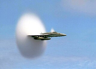
The sound barrier or sonic barrier is the large increase in aerodynamic drag and other undesirable effects experienced by an aircraft or other object when it approaches the speed of sound. When aircraft first approached the speed of sound, these effects were seen as constituting a barrier, making faster speeds very difficult or impossible. The term sound barrier is still sometimes used today to refer to aircraft approaching supersonic flight in this high drag regime. Flying faster than sound produces a sonic boom.

<span class="mw-page-title-main">Swept wing</span> Plane wing that angles backwards or forwards

A swept wing is a wing angled either backward or occasionally forward from its root rather than perpendicular to the fuselage.

<span class="mw-page-title-main">Transonic</span> Flight condition in which airflow speeds are concurrently above and below the speed of sound

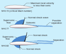
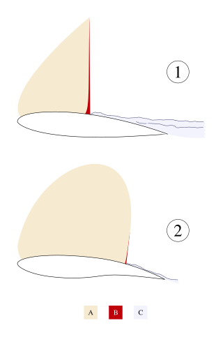
Transonic flow is air flowing around an object at a speed that generates regions of both subsonic and supersonic airflow around that object. The exact range of speeds depends on the object's critical Mach number, but transonic flow is seen at flight speeds close to the speed of sound, typically between Mach 0.8 and 1.2.

In aeronautics, wave drag is a component of the aerodynamic drag on aircraft wings and fuselage, propeller blade tips and projectiles moving at transonic and supersonic speeds, due to the presence of shock waves. Wave drag is independent of viscous effects, and tends to present itself as a sudden and dramatic increase in drag as the vehicle increases speed to the critical Mach number. It is the sudden and dramatic rise of wave drag that leads to the concept of a sound barrier.

<span class="mw-page-title-main">Flight control surfaces</span> Surface that allows a pilot to adjust and control an aircrafts flight attitude

Aircraft flight control surfaces are aerodynamic devices allowing a pilot to adjust and control the aircraft's flight attitude.

<span class="mw-page-title-main">Hans Guido Mutke</span> WWII German fighter pilot

Hans Guido Mutke was a fighter pilot for the German Luftwaffe during World War II. He was born in Neisse, Upper Silesia.

<span class="mw-page-title-main">Elevator (aeronautics)</span> Aircraft control surface used to control pitch

Elevators are flight control surfaces, usually at the rear of an aircraft, which control the aircraft's pitch, and therefore the angle of attack and the lift of the wing. The elevators are usually hinged to the tailplane or horizontal stabilizer. They may be the only pitch control surface present, and are sometimes located at the front of the aircraft or integrated into a rear "all-moving tailplane", also called a slab elevator or stabilator.

<span class="mw-page-title-main">Stabilator</span>

A stabilator is a fully movable aircraft horizontal stabilizer. It serves the usual functions of longitudinal stability, control and stick force requirements otherwise performed by the separate parts of a conventional horizontal stabilizer and elevator. Apart from reduced drag, particularly at high Mach numbers, it is a useful device for changing the aircraft balance within wide limits, and for reducing stick forces.

Aircraft flight mechanics are relevant to fixed wing and rotary wing (helicopters) aircraft. An aeroplane, is defined in ICAO Document 9110 as, "a power-driven heavier than air aircraft, deriving its lift chiefly from aerodynamic reactions on surface which remain fixed under given conditions of flight".

<span class="mw-page-title-main">Critical Mach number</span>

In aerodynamics, the critical Mach number of an aircraft is the lowest Mach number at which the airflow over some point of the aircraft reaches the speed of sound, but does not exceed it. At the lower critical Mach number, airflow around the entire aircraft is subsonic. Supersonic aircraft such as the Concorde and combat aircraft also have an upper critical Mach number at which the airflow around the entire aircraft is supersonic.

<span class="mw-page-title-main">Supercritical airfoil</span> Airfoil designed primarily to delay the onset of wave drag in the transonic speed range

A supercritical aerofoil is an airfoil designed primarily to delay the onset of wave drag in the transonic speed range.

<span class="mw-page-title-main">Stabilizer (aeronautics)</span> Aircraft component

An aircraft stabilizer is an aerodynamic surface, typically including one or more movable control surfaces, that provides longitudinal (pitch) and/or directional (yaw) stability and control. A stabilizer can feature a fixed or adjustable structure on which any movable control surfaces are hinged, or it can itself be a fully movable surface such as a stabilator. Depending on the context, "stabilizer" may sometimes describe only the front part of the overall surface.

<span class="mw-page-title-main">Pitch-up</span>

In aerodynamics, pitch-up is an uncommanded nose-upwards rotation of an aircraft. It is an undesirable characteristic that has been observed mostly in experimental swept-wing aircraft at high subsonic Mach numbers or high angle of attack.

<span class="mw-page-title-main">Canard (aeronautics)</span> Aircraft configuration in which a small wing is placed in front of the main wing

In aeronautics, a canard is a wing configuration in which a small forewing or foreplane is placed forward of the main wing of a fixed-wing aircraft or a weapon. The term "canard" may be used to describe the aircraft itself, the wing configuration, or the foreplane. Canard wings are also extensively used in guided missiles and smart bombs.

<span class="mw-page-title-main">Tailless aircraft</span> Aircraft whose only horizontal aerodynamic surface is its main wing

In aeronautics, a tailless aircraft is an aircraft with no other horizontal aerodynamic surface besides its main wing. It may still have a fuselage, vertical tail fin, and/or vertical rudder.

In flight dynamics, longitudinal stability is the stability of an aircraft in the longitudinal, or pitching, plane. This characteristic is important in determining whether an aircraft pilot will be able to control the aircraft in the pitching plane without requiring excessive attention or excessive strength.

<span class="mw-page-title-main">Trim drag</span> Component of aerodynamic drag on aircraft

Trim drag, denoted as Dm in the diagram, is the component of aerodynamic drag on an aircraft created by the flight control surfaces, mainly elevators and trimable horizontal stabilizers, when they are used to offset changes in pitching moment and centre of gravity during flight. For longitudinal stability in pitch and in speed, aircraft are designed in such a way that the centre of mass is forward of the neutral point. The nose-down pitching moment is compensated by the downward aerodynamic force on the elevator and the trimable horizontal stabilizer. This downwards force on the tailplane produces lift–induced drag in a similar way as the lift on the wing produces lift–induced drag. The changes (shifts) of the position of the centre of mass are often caused by fuel being burned off over the period of the flight, and require the aerodynamic trim force to be adjusted. Systems that actively pump fuel between separate fuel tanks in the aircraft can be used to offset this effect and reduce the trim drag.

References

  1. Aerodynamics For Naval Aviators, Hurt, Revised January 1965, Issued by The Office Of The Chief Of Naval Operations Aviation Training Division, p.219
  2. Pilot's Handbook of Aeronautical Knowledge. U.S. Government Printing Office, Washington D.C.: U.S. Federal Aviation Administration. 2003. pp. 3–37 to 3–38. FAA-8083-25.
  3. 1 2 3 Erickson, Albert (2020-09-25). "Investigation of Driving Moments of a Pursuit Airplane in the Ames 16-Foot High-Speed Wind Tunnel" (PDF). Archived (PDF) from the original on September 25, 2020. Retrieved 2020-12-21.
  4. Obert, Ed (2009). "Aerodynamic Design of Transport Aircraft" (PDF). Archived (PDF) from the original on April 15, 2020. Retrieved November 21, 2020.
  5. Clancy, L.J. (1975) Aerodynamics, section 11.10, Pitman Publishing Limited, London. ISBN   0 273 01120 0
  6. Airplane Flying Handbook. U.S. Government Printing Office, Washington D.C.: U.S. Federal Aviation Administration. 2004. pp. 15–7 to 15–8. FAA-8083-3A.
  7. 1 2 Transonic Aircraft Design Archived 2007-06-14 at the Wayback Machine
  8. "On the accident on 1st June 2009 to the Airbus A330-203" (PDF). bea.aero. July 2012. Retrieved 28 March 2023.
  9. Anderson, John D. Jr. Introduction to Flight, Third Edition, McGraw Hill Book Company, ISBN   0-07-001641-0, Figure 5.17 point c and Figure 5.20
  10. Stack, John (October 1935). "The Combpressibility Burble" (PDF). NACA. Archived (PDF) from the original on April 15, 2020. Retrieved November 21, 2020.
  11. Bodie, Warren M. The Lockheed P-38 Lightning: The Definitive Story of Lockheed's P-38 Fighter. Hayesville, North Carolina: Widewing Publications, 2001, 1991. ISBN   0-9629359-5-6.
  12. Axelson, John (September 4, 1947). "Longitudinal Stability and Control of High-Speed Airplanes with Particular Reference to Dive Recovery" (PDF). NACA. Archived (PDF) from the original on September 24, 2020. Retrieved November 21, 2020.
  13. Abzug and Larrabee, Airplane Stability and Control, Cambridge University Press 2002, ISBN   0-521-02128-6, p.165

PD-icon.svg This article incorporates public domain material from Airplane Flying Handbook. United States Government.
PD-icon.svg This article incorporates public domain material from Pilot's Handbook of Aeronautical Knowledge. United States Government.