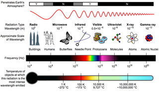
The electromagnetic spectrum is the full range of electromagnetic radiation, organized by frequency or wavelength. The spectrum is divided into separate bands, with different names for the electromagnetic waves within each band. From low to high frequency these are: radio waves, microwaves, infrared, visible light, ultraviolet, X-rays, and gamma rays. The electromagnetic waves in each of these bands have different characteristics, such as how they are produced, how they interact with matter, and their practical applications.

Microwave is a form of electromagnetic radiation with wavelengths shorter than other radio waves but longer than infrared waves. Its wavelength ranges from about one meter to one millimeter, corresponding to frequencies between 300 MHz and 300 GHz, broadly construed. A more common definition in radio-frequency engineering is the range between 1 and 100 GHz, or between 1 and 3000 GHz . The prefix micro- in microwave is not meant to suggest a wavelength in the micrometer range; rather, it indicates that microwaves are small, compared to the radio waves used in prior radio technology.
In electrical engineering, electrical length is a dimensionless parameter equal to the physical length of an electrical conductor such as a cable or wire, divided by the wavelength of alternating current at a given frequency traveling through the conductor. In other words, it is the length of the conductor measured in wavelengths. It can alternately be expressed as an angle, in radians or degrees, equal to the phase shift the alternating current experiences traveling through the conductor.

In electrical engineering, two conductors are said to be inductively coupled or magnetically coupled when they are configured in a way such that change in current through one wire induces a voltage across the ends of the other wire through electromagnetic induction. A changing current through the first wire creates a changing magnetic field around it by Ampere's circuital law. The changing magnetic field induces an electromotive force (EMF) voltage in the second wire by Faraday's law of induction. The amount of inductive coupling between two conductors is measured by their mutual inductance.
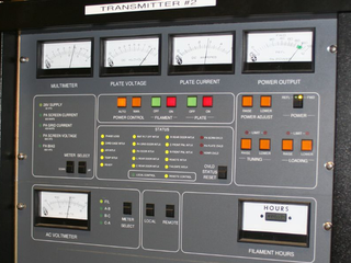
In electronics and telecommunications, a radio transmitter or just transmitter is an electronic device which produces radio waves with an antenna with the purpose of signal transmission up to a radio receiver. The transmitter itself generates a radio frequency alternating current, which is applied to the antenna. When excited by this alternating current, the antenna radiates radio waves.

Radio waves are a type of electromagnetic radiation with the lowest frequencies and the longest wavelengths in the electromagnetic spectrum, typically with frequencies below 300 gigahertz (GHz) and wavelengths greater than 1 millimeter, about the diameter of a grain of rice. Like all electromagnetic waves, radio waves in a vacuum travel at the speed of light, and in the Earth's atmosphere at a slightly slower speed. Radio waves are generated by charged particles undergoing acceleration, such as time-varying electric currents. Naturally occurring radio waves are emitted by lightning and astronomical objects, and are part of the blackbody radiation emitted by all warm objects.
Very low frequency or VLF is the ITU designation for radio frequencies (RF) in the range of 3–30 kHz, corresponding to wavelengths from 100 to 10 km, respectively. The band is also known as the myriameter band or myriameter wave as the wavelengths range from one to ten myriameters. Due to its limited bandwidth, audio (voice) transmission is highly impractical in this band, and therefore only low data rate coded signals are used. The VLF band is used for a few radio navigation services, government time radio stations and for secure military communication. Since VLF waves can penetrate at least 40 meters (131 ft) into saltwater, they are used for military communication with submarines.

In radio engineering, an antenna or aerial is the interface between radio waves propagating through space and electric currents moving in metal conductors, used with a transmitter or receiver. In transmission, a radio transmitter supplies an electric current to the antenna's terminals, and the antenna radiates the energy from the current as electromagnetic waves. In reception, an antenna intercepts some of the power of a radio wave in order to produce an electric current at its terminals, that is applied to a receiver to be amplified. Antennas are essential components of all radio equipment.

The near field and far field are regions of the electromagnetic (EM) field around an object, such as a transmitting antenna, or the result of radiation scattering off an object. Non-radiative near-field behaviors dominate close to the antenna or scatterer, while electromagnetic radiation far-field behaviors predominate at greater distances.
This is an index of articles relating to electronics and electricity or natural electricity and things that run on electricity and things that use or conduct electricity.
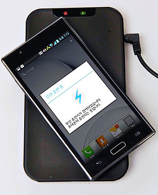
Wireless power transfer (WPT), wireless power transmission, wireless energy transmission (WET), or electromagnetic power transfer is the transmission of electrical energy without wires as a physical link. In a wireless power transmission system, an electrically powered transmitter device generates a time-varying electromagnetic field that transmits power across space to a receiver device; the receiver device extracts power from the field and supplies it to an electrical load. The technology of wireless power transmission can eliminate the use of the wires and batteries, thereby increasing the mobility, convenience, and safety of an electronic device for all users. Wireless power transfer is useful to power electrical devices where interconnecting wires are inconvenient, hazardous, or are not possible.

Electromagnetic interference (EMI), also called radio-frequency interference (RFI) when in the radio frequency spectrum, is a disturbance generated by an external source that affects an electrical circuit by electromagnetic induction, electrostatic coupling, or conduction. The disturbance may degrade the performance of the circuit or even stop it from functioning. In the case of a data path, these effects can range from an increase in error rate to a total loss of the data. Both human-made and natural sources generate changing electrical currents and voltages that can cause EMI: ignition systems, cellular network of mobile phones, lightning, solar flares, and auroras. EMI frequently affects AM radios. It can also affect mobile phones, FM radios, and televisions, as well as observations for radio astronomy and atmospheric science.

A spark-gap transmitter is an obsolete type of radio transmitter which generates radio waves by means of an electric spark. Spark-gap transmitters were the first type of radio transmitter, and were the main type used during the wireless telegraphy or "spark" era, the first three decades of radio, from 1887 to the end of World War I. German physicist Heinrich Hertz built the first experimental spark-gap transmitters in 1887, with which he proved the existence of radio waves and studied their properties.

A loop antenna is a radio antenna consisting of a loop or coil of wire, tubing, or other electrical conductor, that for transmitting is usually fed by a balanced power source or for receiving feeds a balanced load. Within this physical description there are two distinct types:
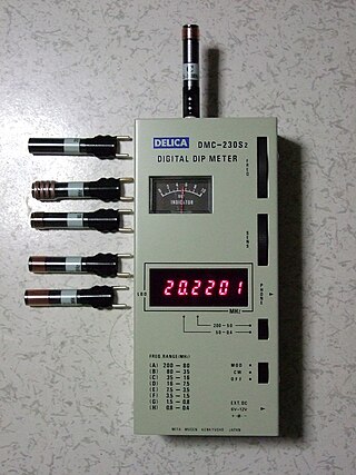
Grid dip oscillator (GDO), also called grid dip meter, gate dip meter, dip meter, or just dipper, is a type of electronic instrument that measures the resonant frequency of nearby unconnected radio frequency tuned circuits. It is a variable-frequency oscillator that circulates a small-amplitude signal through an exposed coil, whose electromagnetic field can interact with adjacent circuitry. The oscillator loses power when its coil is near a circuit that resonates at the same frequency. A meter on the GDO registers the amplitude drop, or "dip", hence the name.

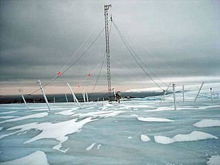
In radio communication, a ground dipole, also referred to as an earth dipole antenna, transmission line antenna, and in technical literature as a horizontal electric dipole (HED), is a huge, specialized type of radio antenna that radiates extremely low frequency (ELF) electromagnetic waves. It is the only type of transmitting antenna that can radiate practical amounts of power in the frequency range of 3 Hz to 3 kHz, commonly called ELF waves. A ground dipole consists of two ground electrodes buried in the earth, separated by tens to hundreds of kilometers, linked by overhead transmission lines to a power plant transmitter located between them. Alternating current electricity flows in a giant loop between the electrodes through the ground, radiating ELF waves, so the ground is part of the antenna. To be most effective, ground dipoles must be located over certain types of underground rock formations. The idea was proposed by U.S. Dept. of Defense physicist Nicholas Christofilos in 1959.
A near-field magnetic induction (NFMI) communication system is a short range wireless physical layer that communicates by coupling a tight, low-power, non-propagating magnetic field between devices. The concept is for a transmitter coil in one device to modulate a magnetic field which is measured by means of a receiver coil in another device.

Resonant inductive coupling or magnetic phase synchronous coupling is a phenomenon with inductive coupling in which the coupling becomes stronger when the "secondary" (load-bearing) side of the loosely coupled coil resonates. A resonant transformer of this type is often used in analog circuitry as a bandpass filter. Resonant inductive coupling is also used in wireless power systems for portable computers, phones, and vehicles.
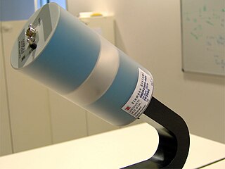
EMF measurements are measurements of ambient (surrounding) electromagnetic fields that are performed using particular sensors or probes, such as EMF meters. These probes can be generally considered as antennas although with different characteristics. In fact, probes should not perturb the electromagnetic field and must prevent coupling and reflection as much as possible in order to obtain precise results. There are two main types of EMF measurements:
In radio systems, many different antenna types are used whose properties are especially crafted for particular applications. Antennas can be classified in various ways. The list below groups together antennas under common operating principles, following the way antennas are classified in many engineering textbooks.

