Multiaxis machining

Last updated
A 5-axis water jet cutter and a part manufactured with it. 5-Axis-Waterjet-Cutting-Head.jpg
A 5-axis water jet cutter and a part manufactured with it.

Multiaxis machining is a manufacturing process that involves tools that move in 4 or more directions and are used to manufacture parts out of metal or other materials by milling away excess material, by water jet cutting or by laser cutting. This type of machining was originally performed mechanically on large complex machines. These machines operated on 4, 5, 6, and even 12 axes which were controlled individually via levers that rested on cam plates. The cam plates offered the ability to control the tooling device, the table in which the part is secured, as well as rotating the tooling or part within the machine. Due to the machines size and complexity it took extensive amounts of time to set them up for production. [1] Once computer numerically controlled machining was introduced it provided a faster, more efficient method for machining complex parts.

Contents

Typical CNC tools support translation in 3 axis; multiaxis machines also support rotation around one or multiple axis. 5-axis machines are commonly used in industry in which the workpiece is translated linearly along three axes (typically x, y, and z) and the tooling spindle is capable of rotation about an addition 2 axes. [2]

There are now many CAM (computer aided manufacturing) software systems available to support multiaxis machining including software that can automatically convert 3-axis toolpaths into 5-axis toolpaths. [3] Prior to the advancement of Computer Aided Manufacturing, transferring information from design to production often required extensive manual labor, generating errors and resulting in wasted time and material.

There are three main components to multiaxis machines:

  1. The machines physical capabilities i.e. torque, spindle speed, axis orientation/operation.
  2. The CNC drive system, the components that move the machine. This includes servo-motors, rapid traverse systems, ball screws, and how positioning is monitored.
  3. The CNC controller, this is how data is transferred/stored within machine, and input data is processed and executed. [4]

Multiaxis machines offer several improvements over other CNC tools, at the cost of increased complexity and price of the machine:

The number of axes for multiaxis machines varies from 4 to 9. [5] Each axis of movement is implemented either by moving the table (into which the workpiece is attached), or by moving the tool. The actual configuration of axes varies, therefore machines with the same number of axes can differ in the movements that can be performed.

Applications

Multiaxis CNC machines are used in many industries including:

Multiaxis machining is also commonly used for rapid prototyping as it can create strong, high quality models out of metal, plastic, and wood while still being easily programmable. [10]

Comparison of different multiaxis machines [11] [12] [13] [14]
Name# of rotary axes on head# of rotary axes on tableAdvantages over other multiaxis machinesDiagram
CNC lathe01 rotating X axis
  • Optimized for machining cylindrical objects
CNC Lathe.png
Pivot spindle head and rotary table1 rotating X axis1 rotating Y axis
  • Able to have a larger work area that increases the versatility of the machine and the kinds of parts it can mill
  • More stable than a Double Pivot Spindle Head
Pivot head and rotary table.png
Double rotary table01 rotating X axis

1 rotating Y axis

  • Best method for milling overhangs
  • Easiest way to convert a 3 axis machine to a 5 axis machine
  • Able to machine higher-volume objects
Double Rotary Table.png
Double pivot spindle head1 rotating Y axis

1 rotating Z axis

0
  • Stationary base allows for heavy parts to be milled
  • Ideal for milling non-round objects
Double pivot head.png
Rotary table and table trunion01 rotating Z axis

1 rotating axis 45° between X & Y axes

  • Similar to a Double Rotary Table, but the 45° axis allows it to be more compact
  • Most cost-effective for machining small parts
Rotary table and table trunnion.png

Computer-aided manufacturing (CAM) software

CAM software automates the process of converting 3D models into tool paths, the route the multiaxis machine takes to mill a part (Fig. 1). This software takes into account the different parameters of the tool head (in the case of a CNC router, this would be the bit size), dimensions of the blank, and any constraints the machine may have. The tool paths for multiple passes can be generated to produce a higher level of detail on the parts. The first few passes remove large amounts of material, while the final, most important pass creates the surface finish. [15] In the case of the CNC lathe, the CAM software will optimize the tool path to have the central axis of the part align with the rotary of the lathe. [16] Once the tool paths have been generated, the CAM software will convert them into G-code, allowing the CNC machine to begin milling. [17] [CNC Factory https://www.cncpartsxtj.com] CAM software is currently the limiting factor in the capabilities of a multiaxis machine with ongoing development. Recent breakthroughs in this space include:

See also

Related Research Articles

<span class="mw-page-title-main">Computer-aided manufacturing</span> Use of software to control industrial processes

Computer-aided manufacturing (CAM) also known as computer-aided modeling or computer-aided machining is the use of software to control machine tools in the manufacturing of work pieces. This is not the only definition for CAM, but it is the most common. It may also refer to the use of a computer to assist in all operations of a manufacturing plant, including planning, management, transportation and storage. Its primary purpose is to create a faster production process and components and tooling with more precise dimensions and material consistency, which in some cases, uses only the required amount of raw material, while simultaneously reducing energy consumption. CAM is now a system used in schools and lower educational purposes. CAM is a subsequent computer-aided process after computer-aided design (CAD) and sometimes computer-aided engineering (CAE), as the model generated in CAD and verified in CAE can be input into CAM software, which then controls the machine tool. CAM is used in many schools alongside CAD to create objects.

<span class="mw-page-title-main">Machine tool</span> Machine for handling or machining metal or other rigid materials

A machine tool is a machine for handling or machining metal or other rigid materials, usually by cutting, boring, grinding, shearing, or other forms of deformations. Machine tools employ some sort of tool that does the cutting or shaping. All machine tools have some means of constraining the workpiece and provide a guided movement of the parts of the machine. Thus, the relative movement between the workpiece and the cutting tool is controlled or constrained by the machine to at least some extent, rather than being entirely "offhand" or "freehand". It is a power-driven metal cutting machine which assists in managing the needed relative motion between cutting tool and the job that changes the size and shape of the job material.

Mastercam is a suite of computer-aided manufacturing (CAM) and CAD/CAM software applications developed by CNC Software, LLC. Founded in Massachusetts in 1983, CNC Software are headquartered in Tolland, Connecticut.

<span class="mw-page-title-main">Shaper</span> Machine tool which linearly cuts or grinds the workpiece

In machining, a shaper is a type of machine tool that uses linear relative motion between the workpiece and a single-point cutting tool to machine a linear toolpath. Its cut is analogous to that of a lathe, except that it is (archetypally) linear instead of helical.

<span class="mw-page-title-main">Numerical control</span> Computer control of machine tools

In machining, numerical control, also called computer numerical control (CNC), is the automated control of tools by means of a computer. It is used to operate tools such as drills, lathes, mills, grinders, routers and 3D printers. CNC transforms a piece of material into a specified shape by following coded programmed instructions and without a manual operator directly controlling the machining operation.

G-code is the most widely used computer numerical control (CNC) and 3D printing programming language. It is used mainly in computer-aided manufacturing to control automated machine tools, as well as for 3D-printer slicer applications. The G stands for geometry. G-code has many variants.

<span class="mw-page-title-main">Tebis</span>

Tebis is a CAD/CAM software provided by Tebis AG, with headquarters in Martinsried near Munich/Germany. Development locations: Martinsried and Norderstedt, Germany International locations: China, Spain, France, Italy, Portugal, Sweden, United Kingdom, USA.

<span class="mw-page-title-main">Tool and cutter grinder</span>

A Tool and Cutter Grinder is used to sharpen milling cutters and tool bits along with a host of other cutting tools.

<span class="mw-page-title-main">Turning</span> Machining process

Turning is a machining process in which a cutting tool, typically a non-rotary tool bit, describes a helix toolpath by moving more or less linearly while the workpiece rotates.

<span class="mw-page-title-main">Metal lathe</span> Machine tool used to remove material from a rotating workpiece

In machining, a metal lathe or metalworking lathe is a large class of lathes designed for precisely machining relatively hard materials. They were originally designed to machine metals; however, with the advent of plastics and other materials, and with their inherent versatility, they are used in a wide range of applications, and a broad range of materials. In machining jargon, where the larger context is already understood, they are usually simply called lathes, or else referred to by more-specific subtype names. These rigid machine tools remove material from a rotating workpiece via the movements of various cutting tools, such as tool bits and drill bits.

<span class="mw-page-title-main">Rotary table</span> Tool used in metalworking

A rotary table is a precision work positioning device used in metalworking. It enables the operator to drill or cut work at exact intervals around a fixed axis. Some rotary tables allow the use of index plates for indexing operations, and some can also be fitted with dividing plates that enable regular work positioning at divisions for which indexing plates are not available. A rotary fixture used in this fashion is more appropriately called a dividing head.

<span class="mw-page-title-main">STEP-NC</span> Machine tool control language

STEP-NC is a machine tool control language that extends the ISO 10303 STEP standards with the machining model in ISO 14649, adding geometric dimension and tolerance data for inspection, and the STEP PDM model for integration into the wider enterprise. The combined result has been standardized as ISO 10303-238.

<span class="mw-page-title-main">CNC router</span> Computer-controlled cutting machine

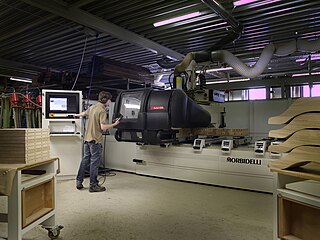
A computer numerical control (CNC) router is a computer-controlled cutting machine which typically mounts a hand-held router as a spindle which is used for cutting various materials, such as wood, composites, metals, plastics, glass, and foams. CNC routers can perform the tasks of many carpentry shop machines such as the panel saw, the spindle moulder, and the boring machine. They can also cut joinery such as mortises and tenons.

<span class="mw-page-title-main">WorkNC</span>

WorkNC is a Computer aided manufacturing (CAM) software developed by Sescoi for multi-axis machining.

<span class="mw-page-title-main">Automatic lathe</span>

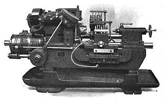
In metalworking and woodworking, an automatic lathe is a lathe with an automatically controlled cutting process. Automatic lathes were first developed in the 1870s and were mechanically controlled. From the advent of NC and CNC in the 1950s, the term automatic lathe has generally been used for only mechanically controlled lathes, although some manufacturers market Swiss-type CNC lathes as 'automatic'.

<span class="mw-page-title-main">Milling (machining)</span> Removal of material from a workpiece using rotating tools

Milling is the process of machining using rotary cutters to remove material by advancing a cutter into a workpiece. This may be done by varying directions on one or several axes, cutter head speed, and pressure. Milling covers a wide variety of different operations and machines, on scales from small individual parts to large, heavy-duty gang milling operations. It is one of the most commonly used processes for machining custom parts to precise tolerances.

<span class="mw-page-title-main">Vericut</span>

Vericut, is a software program used for simulating CNC machining. It is used to simulate tool motion and the material removal process, detecting errors or areas of inefficiency in NC programs. It was developed by CGTech Inc. and first released in 1988.

<span class="mw-page-title-main">Freeform surface machining</span> Machining techniques for complex surfaces

In manufacturing, freeform surface machining refers to the machining of complex surfaces that are not uniformly planar. The industries which most often manufactures free-form surfaces are basically aerospace, automotive, die mold industries, biomedical and power sector for turbine blades manufacturing. Generally 3- or 5-axis CNC milling machines are used for this purpose. The manufacturing process of freeform surfaces is not an easy job, as the tool path generation in present CAM technology is generally based on geometric computation so tool path are not optimum. The geometry can also be not described explicitly so errors and discontinuities occurrence in the solid structure cannot be avoided. Free-form surfaces are machined with the help of different tool path generation method like adaptive iso-planar tool path generation, constant scallop tool path generation, adaptive iso-parametric method, iso-curvature, isophote and by other methods. The different methods are chosen based on the parameters which is needed to be optimized.

<span class="mw-page-title-main">NCSIMUL</span>

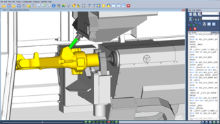
NCSIMUL is a software program developed by the company SPRING Technologies, that is used for simulating, verifying, and optimizing CNC machining in a 3-step process. It reads the post-processed G-code to identify the tool path, and replicates the material removal process of the machine by cutting volumes. It then identifies all syntax errors in the code, crashes in the machining environment, and deviations from the modeled CAD part.

References

  1. Apro, Karlo (2009). Secrets of 5-axis machining. Industrial Press. ISBN   9780831133757. OCLC   1008856747.[ page needed ]
  2. "What Are The Main Applications For 5-Axis CNC Machining? - Kentin Engineering Australia". Kentin Engineering Australia. 2016-05-05. Retrieved 2018-11-17.
  3. MCADCafé. Sescoi's WorkNC 5-Axis and Auto 5 - a competitive advantage at ALLIO .
  4. Saxer, M; De Beer, N; Dimitrov, DM (3 December 2012). "High-speed 5-axis machining for tooling applications". The South African Journal of Industrial Engineering. 23 (3): 144–153. doi: 10.7166/23-3-517 . ProQuest   1269154092.
  5. Karlo Apro (2008). Secrets of 5-Axis Machining . Industrial Press Inc. ISBN   0-8311-3375-9.[ page needed ]
  6. Perry, Clinton (September 2018). "5-axis CNC machines for aerospace". Aerospace Manufacturing And Design. Retrieved 4 April 2024.
  7. "The Precision Use of 5-Axis CNC Machining in Automotive Industry". www.waykenrm.com. 30 October 2018. Retrieved 2020-11-15.
  8. "Specialist CNC machining solutions". Furniture & Joinery Production. Retrieved 2020-11-15.
  9. Duncan Thompson (December 2021). "On the ball with hip implants". The World's Most Flexible Tool Grinder - ANCA - CNC Machines. Retrieved 26 September 2023.
  10. "Why People Like To Use 5 Axis CNC Machine In Rapid Prototyping?". www.ltc-proto.com. Retrieved 2020-11-16.
  11. "What is CNC Lathe Machine and what its function?". Worthy Hardware. 2017-08-09. Retrieved 2020-10-22.
  12. "Everything You Need To Know About 5-Axis CNC Machining". www.waykenrm.com. Retrieved 2020-10-25.
  13. "Machine Configurations". What is 5-Axis CNC Machining & Programming. Retrieved 2020-11-15.
  14. "Four Types Of Five-Axis Machining Centers". www.mmsonline.com. Retrieved 2020-11-15.
  15. Chang, Kuang-Hua, 1960- (2013). Product manufacturing and cost estimating using CAD/CAE. Oxford, UK: Academic Press. ISBN   978-0-12-404600-9. OCLC   868597615.{{cite book}}: CS1 maint: multiple names: authors list (link) CS1 maint: numeric names: authors list (link)[ page needed ]
  16. Kawaguchi, Yasuhiro; Nakamoto, Keiichi; Ishida, Toru; Takeuchi, Yoshimi (2009). "C8 Artistic Machining by Means of Multi-tasking Machine(Multi-axis control machining)". Proceedings of International Conference on Leading Edge Manufacturing in 21st Century : Lem21. 2009 (5): 145–148. doi:10.1299/jsmelem.2009.5.145.
  17. Dejan (2020-05-06). "G-code Explained | List of Most Important G-code Commands". HowToMechatronics. Retrieved 2020-11-15.
  18. Mirzendehdel, Amir M.; Behandish, Morad; Nelaturi, Saigopal (May 2020). "Topology optimization with accessibility constraint for multi-axis machining". Computer-Aided Design. 122: 102825. arXiv: 2002.07627 . doi:10.1016/j.cad.2020.102825. S2CID   211146708.
  19. Manufacturing science and technology VI : Selected, peer reviewed papers from the 2015 6th International Conference on Manufacturing Science and Technology (ICMST 2015), June 1-2, 2015, Bandar Seri Begawan, Brunei. De Silva, Liyanage C.,, Debnath, Sujan,, Reddy, M. Mohan. [Zurich], Switzerland. ISBN   978-3-0357-0014-5. OCLC   921032943.{{cite book}}: CS1 maint: others (link)[ page needed ]