Nutating disc engine

Last updated
Operation of the Dakeyne nutating disk engine Dakeyne disc engine animation.gif
Operation of the Dakeyne nutating disk engine

A nutating disc engine (also sometimes called a disc engine) is an internal combustion engine comprising fundamentally of one moving part and a direct drive onto the crankshaft. Initially patented in 1993, it differs from earlier internal combustion engines in a number of ways and uses a circular rocking or wobbling nutating motion , drawing heavily from similar steam-powered engines developed in the 19th century, and similar to the motion of the non-rotating portion of a swash plate on a swash plate engine.

Contents

Operation

In its basic configuration the core of the engine is a nutating non-rotating disc, with the center of its hub mounted in the middle of a Z-shaped shaft. The two ends of the shaft rotate, while the disc "nutates" (performs a wobbling motion without rotating around its axis). The motion of the disc circumference describes a portion of a sphere. A portion of the area of the disc is used for intake and compression, a portion is used to seal against a center casing, and the remaining portion is used for expansion and exhaust. The compressed air is admitted to an external accumulator, and then into an external combustion chamber before it is admitted to the power side of the disc. The external combustion chamber enables the engine to use diesel fuel in small engine sizes, giving it unique capabilities for unmanned aerial vehicle propulsion and other applications. One significant benefit of the nutating engine is the overlap of the power strokes.

Power is transmitted directly to the output shaft (the crankshaft), completely eliminating the need for complicated linkages essential in a conventional piston engine (to convert the piston's linear motion to rotating output motion). Since the disc does not rotate, the seal velocities are lower than in an equivalent IC piston engine. The total seal length is rather long, however, which may negate this advantage.

The disc wobbles inside a housing and, in its simplest version, half of the single disc (one lobe) performs the intake/compression function while the other lobe performs the power/exhaust function. The disc lobes can be configured to have equal compression and expansion volumes, or to have the compression volume greater than or less than the expansion volume. This means that the engine can be self supercharged (see supercharger), or operate as a Miller cycle / Atkinson cycle.

Patents and production history

U.S. patent number 5,251,594 was granted to Leonard Meyer of Illinois in 1993 for a "nutating internal combustion disc engine". [1] The Meyer Nutating Engine is a new type of internal combustion engine with higher power density than conventional reciprocating piston engines and which can operate on a variety of fuels, including gasoline, heavy fuels and hydrogen. The patent made reference to various 20th-century nutating engines in the United States, but no reference at all to the original Dakeyne engine, described below, in its prior art. The similarity to its 166-year-old hydraulic predecessor is strikingly evident, the main change being that the disc is not entirely flat but slightly convex.

The details of operation and potential of the Meyer nutating disk engine have been described by Professor T. Alexander (publishes as T. Korakianitis) and co-workers. [2] [3] [4] [5]

A single prototype has been run briefly under its own power, with a power- to-weight ratio equal to those of typical current four-stroke engines. It is claimed by the authors of the developer/US Army Research Laboratory/NASA technical evaluation report that a production version of the new engine (for UAV applications) might provide a power-to-weight ratio of 1.6 hp/lb or 2.7 kW/kg. [6] This is slightly better than current automotive production engines [7] but nowhere near the Graupner G58 [8] or the Desert Air DA 150. [9]

A company called McMasters, previously headed by successful American entrepreneur Harold McMaster, is also developing a nutating motor burning a mixture of pure hydrogen and pure oxygen that, it claims, will give 200 hp but weigh only one-tenth that of gasoline/air production automotive engines with the same output. So far the McMasters company claims to have spent $10 million on its development. Plans are also being made to develop a version "the size of a coffee can" that can be built directly into wheel hubs, eliminating the traditional drive train entirely. This concept was first attempted in the British Leyland Mini Moke [ citation needed ] but was, at that time, severely hampered by lack of reliable synchronization – which is now more commonplace because of ubiquitous miniaturized embedded modern-day computer chips. A gasoline-powered version is also planned by McMasters, which is claimed to give substantially cleaner operation than traditional engines. [10]

History

Dakeyne hydraulic disc engine

In the 1820s the mill owners Edward and James Dakeyne of Darley Dale, Derbyshire, designed and had constructed a hydraulic engine (a water engine) known as "The Romping Lion", based on the same principles, to make use of the high-pressure water available near their mill. Little is known of their engine other than from the somewhat unclear description accompanying the patent, which was granted in 1830. Its main castings were made at the Morley Park foundry near Heage, and it weighed 7 tons and generated 35 horsepower at a head of 96 feet of water. Frank Nixon in his book "The Industrial Archaeology of Derbyshire" (1969) commented that "The most striking characteristic of this ingenious machine is perhaps the difficulty experienced by those trying to describe it; the patentees & Stephen Glover only succeeded in producing descriptions of monumental incomprehensibility". [11]

A larger model was constructed to drain lead mines at Alport near Youlgreave and many steam versions were subsequently built by other people.

Davies and Taylor

The first people to develop steam-powered disc engines based on the Dakeynes' design were George Davies and Henry Taylor who patented their engine in 1836. It was fitted with valves to control the admission of steam and also differed from the Dakeynes' version in that the axis of the engine was horizontal and the casing of the engine rotated around the disc, the opposite of the original. More patents followed over the next eight years, mainly introducing expansive working and improving the engine's sealing.

In 1836 Davies and Taylor granted manufacturing rights for the engine to Fardon and Gossage, owners of a salt works. At the same time Davies was working on a canal tug with a disc engine driving a paddle wheel at the stern. By 1838 a 5 hp engine was in use at the salt works pumping brine.

In 1839 Davies, Taylor, Fardon and Gossage conveyed manufacturing rights to the engine to the Birmingham Patent Disc Engine company. As Superintendent of the Company, Henry Davies was responsible for all design and manufacture, while Gossage was a director. In February 1841 the Board reported that 26 engines had been completed, further engines totalling 260 horsepower were in progress, and a total of 500 horsepower were on order. They could make engines ranging from 5 to 30 horsepower and were currently making engines for a railway carriage. An article in a French journal of 1841 reported that a 12 hp engine had been in use for six months as a winding engine at Corbyn's Hall Mine, Dudley, which could lift a load of 1 ton 180 ft in 1 minute. The disc engines cost from £96 for an 8 hp machine to £300 for a 30 hp model.

Ransomes of Ipswich (who were later to become the well-known agricultural engineers Ransomes and Sims) exhibited a portable steam engine at the Royal Liverpool Show in 1841, powered by a 5 hp BPDE disc engine.

By 1840 a canal boat, The Experiment, powered by a Davies engine, was being used for propeller testing, and in 1842 Davies installed a disc engine and disc pump in a canal barge which he demonstrated by draining half a mile of the Stourbridge canal. The same year, a 5 hp engine was fitted in one of HMS Geyser's pinnaces. However, trials on the Thames and for the Directors of the Grand Junction Canal failed to convince either the Admiralty or the canal owners.

Nevertheless, there was a growing interest in using steam power on the canals, and the small beam of canal boats very much favoured disc engines. Davies saw his opportunity and built an iron-hulled canal tug with a 16 hp BPDE engine in 1843. To minimise wash he fitted four propellers spaced along a shaft the length of the boat and enclosed in a tube below the waterline. There were two of these propulsion units side by side for a total of 8 propellers. It worked well enough to convince the Directors of the Birmingham and Liverpool Junction Canal to order six tugs which could tow as many as sixteen barges a day at a reasonable speed. In use, a train of six to eight barges left Ellesmere Port and Wolverhampton each day, carrying an average of 100 tons. Unfortunately nobody had considered how the barge train was to transit through the canal locks and shallows. Each such obstruction meant that the train had to be uncoupled and the barges individually manhandled or towed by horse through the obstruction before the train was reassembled on the other side. This negated the benefits of the tug and train and in 1845 the canal's Directors removed the tugs from service.

In 1844 the BPDE collapsed. [12] The workshop equipment, various completed engines and quantities of work in progress were offered for sale. During legal proceedings in 1851 following the bankruptcy of two of the BPDE's principal investors, it was said that the disc engine had not made a profit and that to have relied on it as a realisable asset "was absurd".

Bishopp

A competitor to Davies and Taylor was former locomotive engineer George Daniell Bishopp, who had Donkin & Co build his first engine in 1840, and a patent was granted in 1845. The partners Barnard William Farey and Bryan Donkin Jr. patented improvements to the basic design; Donkin had worked with Bishopp on his original engine, while Farey was an employee of Donkins.

Bishopp's engine met with some scepticism from the trade press when it was launched on the market. But Bishopp had opted to revert to the Dakeynes' original design which had a yoke which took most of the dynamic forces and greatly reduced the load on the bearings and seals. In the event that there was any leakage, the seals were adjustable. In addition, Bishopp had his engines produced by companies with recognised engineering capabilities rather than carrying out his own manufacturing; as well as Donkin's, some of his first engines were built by Joseph Whitworth & Co of Manchester. Another engineering company with a very good reputation was G. Rennie and Son of London who were so convinced of the engine's potential that in 1849 they employed Bishopp as their foreman of works with specific responsibility for the disc engine.

By 1849 a number of Bishopp engines had been sold, and one was used with great success to run the printing presses of the Times newspaper, while another produced by G. Rennie and Son was used to power the iron gunboat HMS Minx. The Times engine had been built by Whitworth and had been shown at the Great Exhibition of 1851 where it ran smoothly and quietly and impressed all who saw it.

In 1853 a disc engine 13 inches in diameter was purchased from Rennie to propel a 55 foot Russian gunboat, which it did at a speed of 7 knots (13 km/h; 8.1 mph). [13]

At the time the advantages of the disc engine were listed in 1855 by The Mechanics' Magazine as: [13]

Disc engines ultimately fell into disuse because of competition from modern high-speed steam engines, which were small and light and could offer features such as compounding. Additionally, conventional engines did not require the same precision manufacture as disc engines and steam leakage was not a problem.

Water meters

The nutating disc meter, which uses the same geometry and concept as the Dakeynes' original engine, [14] [15] is probably the most widely used flowmeter in the world, and it is claimed that more than half the water meters installed in domestic premises in the US and Europe are of this type. Used for 150 years, it is essentially a Dakeyne Disc Engine and was most probably developed by Farey and Donkin who mentioned a "fluid measurement meter" in their 1850 disc engine patent granted in 1850. By 1859 they were being manufactured by the Buffalo Meter Company of Buffalo, New York.

See also

Related Research Articles

<span class="mw-page-title-main">Tesla turbine</span> Bladeless centripetal flow turbine

The Tesla turbine is a bladeless centripetal flow turbine patented by Nikola Tesla on October 21,1913. It was his 100th patent.

<span class="mw-page-title-main">Sleeve valve</span> Valve mechanism for piston engines

The sleeve valve is a type of valve mechanism for piston engines, distinct from the usual poppet valve. Sleeve valve engines saw use in a number of pre–World War II luxury cars and in the United States in the Willys-Knight car and light truck. They subsequently fell from use due to advances in poppet-valve technology, including sodium cooling, and the Knight system double sleeve engine's tendency to burn a lot of lubricating oil or to seize due to lack of it. The Scottish Argyll company used its own, much simpler and more efficient, single sleeve system (Burt-McCollum) in its cars, a system which, after extensive development, saw substantial use in British aircraft engines of the 1940s, such as the Napier Sabre, Bristol Hercules, Centaurus, and the promising but never mass-produced Rolls-Royce Crecy, only to be supplanted by the jet engines.

<span class="mw-page-title-main">Tugboat</span> Boat that maneuvers other vessels by pushing or towing them

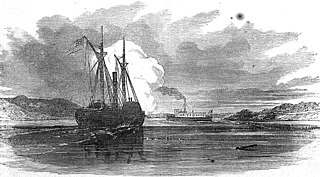
A tugboat or tug is a marine vessel that manoeuvres other vessels by pushing or pulling them, with direct contact or a tow line. These boats typically tug ships in circumstances where they cannot or should not move under their own power, such as in crowded harbors or narrow canals, or cannot move at all, such as barges, disabled ships, log rafts, or oil platforms. Some are ocean-going, and some are icebreakers or salvage tugs. Early models were powered by steam engines, which were later superseded by diesel engines. Many have deluge gun water jets, which help in firefighting, especially in harbours.

<i>Charlotte Dundas</i>

Charlotte Dundas is regarded as the world's second successful steamboat, the first towing steamboat and the boat that demonstrated the practicality of steam power for ships.

<span class="mw-page-title-main">Rotary valve</span>

A rotary valve is a type of valve in which the rotation of a passage or passages in a transverse plug regulates the flow of liquid or gas through the attached pipes. The common stopcock is the simplest form of rotary valve. Rotary valves have been applied in numerous applications, including:

Improvements to the steam engine were some of the most important technologies of the Industrial Revolution, although steam did not replace water power in importance in Britain until after the Industrial Revolution. From Englishman Thomas Newcomen's atmospheric engine, of 1712, through major developments by Scottish inventor and mechanical engineer James Watt, the steam engine began to be used in many industrial settings, not just in mining, where the first engines had been used to pump water from deep workings. Early mills had run successfully with water power, but by using a steam engine a factory could be located anywhere, not just close to a water source. Water power varied with the seasons and was not always available.

<span class="mw-page-title-main">Pistonless rotary engine</span> Internal combustion engine

A pistonless rotary engine is an internal combustion engine that does not use pistons in the way a reciprocating engine does. Designs vary widely but typically involve one or more rotors, sometimes called rotary pistons. Although many different designs have been constructed, only the Wankel engine has achieved widespread adoption.

<span class="mw-page-title-main">Indicator diagram</span> Used to estimate the performance of reciprocating engine

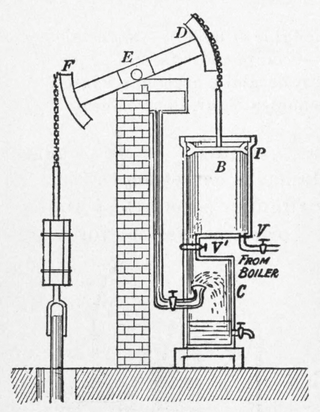
An indicator diagram is a chart used to measure the thermal, or cylinder, performance of reciprocating steam and internal combustion engines and compressors. An indicator chart records the pressure in the cylinder versus the volume swept by the piston, throughout the two or four strokes of the piston which constitute the engine, or compressor, cycle. The indicator diagram is used to calculate the work done and the power produced in an engine cylinder or used in a compressor cylinder.

The Dakeyne hydraulic disc engine was a high-pressure hydraulic engine built in the 19th century to power a flax mill in Ladygrove, Derbyshire, England.

<span class="mw-page-title-main">Beam engine</span> Early configuration of the steam engine utilising a rocking beam to connect major components.

A beam engine is a type of steam engine where a pivoted overhead beam is used to apply the force from a vertical piston to a vertical connecting rod. This configuration, with the engine directly driving a pump, was first used by Thomas Newcomen around 1705 to remove water from mines in Cornwall. The efficiency of the engines was improved by engineers including James Watt, who added a separate condenser; Jonathan Hornblower and Arthur Woolf, who compounded the cylinders; and William McNaught, who devised a method of compounding an existing engine. Beam engines were first used to pump water out of mines or into canals but could be used to pump water to supplement the flow for a waterwheel powering a mill.

<span class="mw-page-title-main">Axial engine</span>

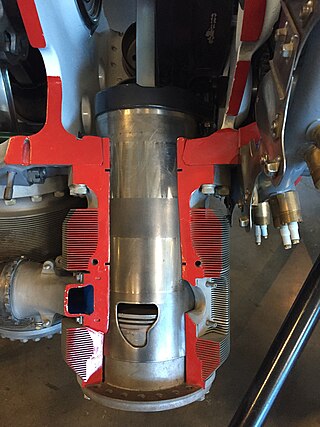
An axial engine is a type of reciprocating engine with pistons arranged around an output shaft with their axes parallel to the shaft. Barrel refers to the cylindrical shape of the cylinder group whilst the Z-crank alludes to the shape of the crankshaft.

<span class="mw-page-title-main">Étienne Lenoir</span> Belgian-French engineer (1822–1900)

Jean Joseph Étienne Lenoir, also known as Jean J. Lenoir, was a Belgian-French engineer who developed the internal combustion engine in 1858. Prior designs for such engines were patented as early as 1807, but none were commercially successful. Lenoir's engine was commercialized in sufficient quantities to be considered a success, a first for the internal combustion engine.

A swing-piston engine is a type of internal combustion engine in which the pistons move in a circular motion inside a ring-shaped "cylinder", moving closer and further from each other to provide compression and expansion. Generally two sets of pistons are used, geared to move in a fixed relationship as they rotate around the cylinder. In some versions the pistons oscillate around a fixed center, as opposed to rotating around the entire engine. The design has also been referred to as a oscillating piston engine, vibratory engine when the pistons oscillate instead of rotate, or toroidal engine based on the shape of the "cylinder".

<span class="mw-page-title-main">Swashplate</span> Mechanism to convert between reciprocating and rotary motion

A swashplate, also known as slant disk, is a mechanical engineering device used to translate the motion of a rotating shaft into reciprocating motion, or vice versa. The working principle is similar to crankshaft, Scotch yoke, or wobble/nutator/Z-crank drives, in engine designs. It was originally invented to replace a crankshaft, and is one of the most popular concepts used in crankless engines. It was invented by Anthony Michell in 1917.

<span class="mw-page-title-main">Arthur Woolf</span> Cornish engineer (1766-1837)

Arthur Woolf was a Cornish engineer, most famous for inventing a high-pressure compound steam engine. In this way he made an outstanding contribution to the development and perfection of the Cornish engine.

<span class="mw-page-title-main">Scotch marine boiler</span> Design of steam boiler best known for its use on ships

A "Scotch" marine boiler is a design of steam boiler best known for its use on ships.

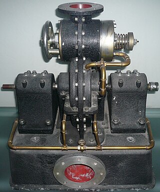
J. and G. Rennie was a British engineering company based in Millwall, London, England. They were involved in manufacture of marine engines, and some complete ships, as well as other diverse onshore engineering projects. An association with railway engines is usually attributed to G. and J. Rennie, which may suggest they used a second company to keep the books separate, and there was also George Rennie & Sons, which is associated with the development and patents of the steam disc engine. All three companies appear to have been in existence at the same time.

<span class="mw-page-title-main">Single- and double-acting cylinders</span> Classification of reciprocating engine cylinders

In mechanical engineering, the cylinders of reciprocating engines are often classified by whether they are single- or double-acting, depending on how the working fluid acts on the piston.

In engineering, a nutating motion is similar to that seen in a swashplate mechanism. In general, a nutating plate is carried on a skewed bearing on the main shaft and does not itself rotate, whereas a swashplate is fixed to the shaft and rotates with it. The motion is similar to the motions of coin or a tire wobbling on the ground after being dropped with the flat side down. Precession is the physical term for this kind of motion.


The five-stroke engine is a compound internal combustion engine patented by Gerhard Schmitz in 2000. Schmitz's concept is being developed by Ilmor Engineering. Ilmor's prototype is an internal combustion engine that uses a solid cylinder block with electric motors driving the oil and water cooling pumps. The prototype uses two overhead camshafts with standard poppet valves. The five-stroke prototype engine is turbocharged. The goal of the five-stroke engine is to have higher efficiency with lower fuel use. In order to increase efficiency, a secondary cylinder is added as an expansion processor to extract more energy from the fuel.

References

  1. USpatent 5,251,594,Meyer, Leonard,"Nutating internal combustion engine",issued 1993-10-12
  2. Korakianitis, T.; Meyer, L.; Boruta, M.; McCormick, H. E. (April 2004). "Introduction and performance prediction of a nutating-disk engine". Journal of Engineering for Gas Turbines and Power. 126 (2): 294–99. doi:10.1115/1.1635394.
  3. Korakianitis, T.; Meyer, L.; Boruta, M.; McCormick, H. E. (July 2004). "One-disk nutating-engine performance for unmanned aerial vehicles". Journal of Engineering for Gas Turbines and Power. 126 (3): 475–81. doi:10.1115/1.1496770.
  4. Korakianitis, T.; Meyer, L.; Boruta, M.; McCormick, H. E. (July 2004). "Alternative multi-nutating-disk engine configurations for diverse applications". Journal of Engineering for Gas Turbines and Power. 126 (3): 482–88. doi:10.1115/1.1688770.
  5. Korakianitis, T.; Meyer, L.; Boruta, M.; Jerovsek, J.; Meitner, P. L. (October 2009). "Performance of a single nutating disk engine in the 2 to 500 kW power range". Applied Energy. 86 (10): 2213–21. doi:10.1016/j.apenergy.2009.01.006.
  6. The Nutating Engine—Prototype Engine Progress Report and Test Results, (Peter L. Meitner, U.S. Army Research Laboratory, Glenn Research Center, Cleveland, Ohio),(Mike Boruta and Jack Jerovsek, KINETIC/BEI LLC, South Elgin, Illinois) NASA/TM—2006-214342 ARL–MR–0641 U.S. ARMY RESEARCH LABORATORY, Fig. 6.
  7. Sports Car Designer [ dead link ]
  8. "Two stroke engines for UAV: info collected by BML". Archived from the original on 2009-03-01. Retrieved 2007-12-31.
  9. "Desert Aircraft". Archived from the original on 2007-09-17. Retrieved 2007-12-31.
  10. McMaster Motor
  11. Nixon, Frank (1969). The Industrial Archaeology of Derbyshire. David & Charles. p. 102.
  12. Burn, Robert Scott (1857). The Steam Engine. London: Ward and Lock. pp. 108–109.
  13. 1 2 The Mechanics' Magazine. London: Robertson, Brooman, and Co. 1855. pp.  267–268.
  14. Niagara Meters: Nutating Disc Drawing
  15. Hersey Meters – 400 Series Positive Displacement Disc Water Meter
History
Technical reports