Related Research Articles

Rendering or image synthesis is the process of generating a photorealistic or non-photorealistic image from a 2D or 3D model by means of a computer program. The resulting image is referred to as the render. Multiple models can be defined in a scene file containing objects in a strictly defined language or data structure. The scene file contains geometry, viewpoint, texture, lighting, and shading information describing the virtual scene. The data contained in the scene file is then passed to a rendering program to be processed and output to a digital image or raster graphics image file. The term "rendering" is analogous to the concept of an artist's impression of a scene. The term "rendering" is also used to describe the process of calculating effects in a video editing program to produce the final video output.

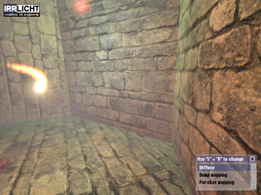
Texture mapping is a method for mapping a texture on a computer-generated graphic. Texture here can be high frequency detail, surface texture, or color.

In 3D computer graphics, normal mapping, or Dot3 bump mapping, is a texture mapping technique used for faking the lighting of bumps and dents – an implementation of bump mapping. It is used to add details without using more polygons. A common use of this technique is to greatly enhance the appearance and details of a low polygon model by generating a normal map from a high polygon model or height map.

Shadow volume is a technique used in 3D computer graphics to add shadows to a rendered scene. They were first proposed by Frank Crow in 1977 as the geometry describing the 3D shape of the region occluded from a light source. A shadow volume divides the virtual world in two: areas that are in shadow and areas that are not.

Ray casting is the methodological basis for 3D CAD/CAM solid modeling and image rendering. It is essentially the same as ray tracing for computer graphics where virtual light rays are "cast" or "traced" on their path from the focal point of a camera through each pixel in the camera sensor to determine what is visible along the ray in the 3D scene. The term "Ray Casting" was introduced by Scott Roth while at the General Motors Research Labs from 1978–1980. His paper, "Ray Casting for Modeling Solids", describes modeled solid objects by combining primitive solids, such as blocks and cylinders, using the set operators union (+), intersection (&), and difference (-). The general idea of using these binary operators for solid modeling is largely due to Voelcker and Requicha's geometric modelling group at the University of Rochester. See solid modeling for a broad overview of solid modeling methods. This figure on the right shows a U-Joint modeled from cylinders and blocks in a binary tree using Roth's ray casting system in 1979.

In 3D computer graphics, hidden-surface determination is the process of identifying what surfaces and parts of surfaces can be seen from a particular viewing angle. A hidden-surface determination algorithm is a solution to the visibility problem, which was one of the first major problems in the field of 3D computer graphics. The process of hidden-surface determination is sometimes called hiding, and such an algorithm is sometimes called a hider. When referring to line rendering it is known as hidden-line removal. Hidden-surface determination is necessary to render a scene correctly, so that one may not view features hidden behind the model itself, allowing only the naturally viewable portion of the graphic to be visible.
2.5D perspective refers to gameplay or movement in a video game or virtual reality environment that is restricted to a two-dimensional (2D) plane with little or no access to a third dimension in a space that otherwise appears to be three-dimensional and is often simulated and rendered in a 3D digital environment.
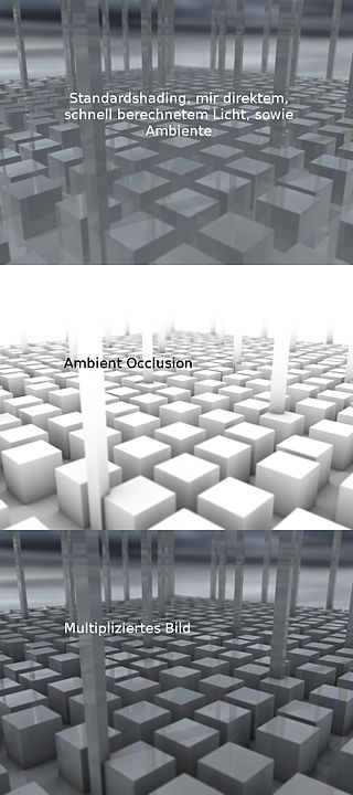
In 3D computer graphics, modeling, and animation, ambient occlusion is a shading and rendering technique used to calculate how exposed each point in a scene is to ambient lighting. For example, the interior of a tube is typically more occluded than the exposed outer surfaces, and becomes darker the deeper inside the tube one goes.

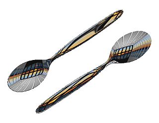
Subsurface scattering (SSS), also known as subsurface light transport (SSLT), is a mechanism of light transport in which light that penetrates the surface of a translucent object is scattered by interacting with the material and exits the surface at a different point. The light will generally penetrate the surface and be reflected a number of times at irregular angles inside the material before passing back out of the material at a different angle than it would have had if it had been reflected directly off the surface.
In computer graphics, environment mapping, or reflection mapping, is an efficient image-based lighting technique for approximating the appearance of a reflective surface by means of a precomputed texture. The texture is used to store the image of the distant environment surrounding the rendered object.
Clipping, in the context of computer graphics, is a method to selectively enable or disable rendering operations within a defined region of interest. Mathematically, clipping can be described using the terminology of constructive geometry. A rendering algorithm only draws pixels in the intersection between the clip region and the scene model. Lines and surfaces outside the view volume are removed.
In computer graphics, per-pixel lighting refers to any technique for lighting an image or scene that calculates illumination for each pixel on a rendered image. This is in contrast to other popular methods of lighting such as vertex lighting, which calculates illumination at each vertex of a 3D model and then interpolates the resulting values over the model's faces to calculate the final per-pixel color values.
In computer graphics, relief mapping is a texture mapping technique first introduced in 2000 used to render the surface details of three-dimensional objects accurately and efficiently. It can produce accurate depictions of self-occlusion, self-shadowing, and parallax. It is a form of short-distance ray tracing done in a pixel shader. Relief mapping is highly comparable in both function and approach to another displacement texture mapping technique, Parallax occlusion mapping, considering that they both rely on ray tracing, though the two are not to be confused with each other, as parallax occlusion mapping uses reverse heightmap tracing.

Terrain cartography or relief mapping is the depiction of the shape of the surface of the Earth on a map, using one or more of several techniques that have been developed. Terrain or relief is an essential aspect of physical geography, and as such its portrayal presents a central problem in cartographic design, and more recently geographic information systems and geovisualization.

Kerkythea is a standalone rendering system that supports raytracing and Metropolis light transport, uses physically accurate materials and lighting, and is distributed as freeware. Currently, the program can be integrated with any software that can export files in obj and 3ds formats, including 3ds Max, Blender, LightWave 3D, SketchUp, Silo and Wings3D.
Parallax scanning depth enhancing imaging methods rely on discrete parallax differences between depth planes in a scene. The differences are caused by a parallax scan. When properly balanced (tuned) and displayed, the discrete parallax differences are perceived by the brain as depth.
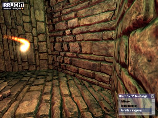
Parallax occlusion mapping (POM) is an enhancement of the parallax mapping technique. Parallax occlusion mapping is used to procedurally create 3D definition in textured surfaces, using a displacement map instead of through the generation of new geometry. This allows developers of 3D rendering applications to add 3D complexity in textures, which correctly change relative to perspective and with self occlusion in real time, without sacrificing the processor cycles required to create the same effect with geometry calculations.
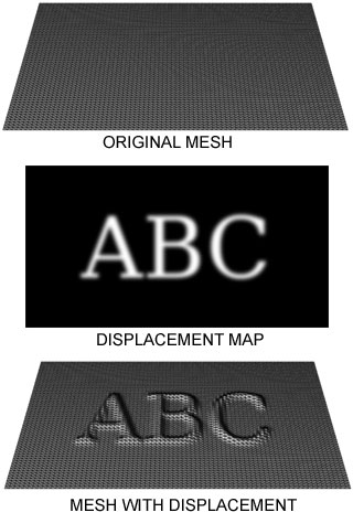
Displacement mapping is an alternative computer graphics technique in contrast to bump, normal, and parallax mapping, using a texture or height map to cause an effect where the actual geometric position of points over the textured surface are displaced, often along the local surface normal, according to the value the texture function evaluates to at each point on the surface. It gives surfaces a great sense of depth and detail, permitting in particular self-occlusion, self-shadowing and silhouettes; on the other hand, it is the most costly of this class of techniques owing to the large amount of additional geometry.
2D to 3D video conversion is the process of transforming 2D ("flat") film to 3D form, which in almost all cases is stereo, so it is the process of creating imagery for each eye from one 2D image.
This is a glossary of terms relating to computer graphics.
References
- ↑ Kaneko, T., et al., 2001. Detailed Shape Representation with Parallax Mapping. In Proceedings of ICAT 2001, pp. 205-208.
- ↑ Tatarchuk, N., 2005. Practical Dynamic Parallax Occlusion Mapping Archived 2009-09-25 at the Wayback Machine Siggraph presentations