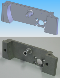
Computer-aided manufacturing (CAM) also known as computer-aided modeling or computer-aided machining is the use of software to control machine tools and related ones in the manufacturing of work pieces. This is not the only definition for CAM, but it is the most common; CAM may also refer to the use of a computer to assist in all operations of a manufacturing plant, including planning, management, transportation and storage. Its primary purpose is to create a faster production process and components and tooling with more precise dimensions and material consistency, which in some cases, uses only the required amount of raw material, while simultaneously reducing energy consumption. CAM is now a system used in schools and lower educational purposes. CAM is a subsequent computer-aided process after computer-aided design (CAD) and sometimes computer-aided engineering (CAE), as the model generated in CAD and verified in CAE can be input into CAM software, which then controls the machine tool. CAM is used in many schools alongside computer-aided design (CAD) to create objects.
Mastercam is a suite of Computer-Aided Manufacturing (CAM) and CAD/CAM software applications. Founded in MA in 1983, CNC Software, LLC is one of the oldest developers of PC-based computer-aided design / computer-aided manufacturing (CAD/CAM) software. They are one of the first to introduce CAD/CAM software designed for both machinists and engineers. Mastercam, CNC Software's main product, started as a 2D CAM system with CAD tools that let machinists design virtual parts on a computer screen and also guided computer numerical controlled (CNC) machine tools in the manufacture of parts. Since then, Mastercam has grown into the most widely used CAD/CAM package in the world. CNC Software, LLC is now located in Tolland, Connecticut.

A shaper is a type of machine tool that uses linear relative motion between the workpiece and a single-point cutting tool to machine a linear toolpath. Its cut is analogous to that of a lathe, except that it is (archetypally) linear instead of helical.

Machining is a process in which a material is cut to a desired final shape and size by a controlled material-removal process. The processes that have this common theme are collectively called subtractive manufacturing, in contrast to additive manufacturing, which uses controlled addition of material. Exactly what the "controlled" part of the definition implies can vary, but it usually implies the use of machine tools.
G-code is the most widely used computer numerical control (CNC) programming language. It is used mainly in computer-aided manufacturing to control automated machine tools, and has many variants.

Diamond turning is turning using a cutting tool with a diamond tip. It is a process of mechanical machining of precision elements using lathes or derivative machine tools equipped with natural or synthetic diamond-tipped tool bits. The term single-point diamond turning (SPDT) is sometimes applied, although as with other lathe work, the "single-point" label is sometimes only nominal. The process of diamond turning is widely used to manufacture high-quality aspheric optical elements from crystals, metals, acrylic, and other materials. Plastic optics are frequently molded using diamond turned mold inserts. Optical elements produced by the means of diamond turning are used in optical assemblies in telescopes, video projectors, missile guidance systems, lasers, scientific research instruments, and numerous other systems and devices. Most SPDT today is done with computer numerical control (CNC) machine tools. Diamonds also serve in other machining processes, such as milling, grinding, and honing. Diamond turned surfaces have a high specular brightness and require no additional polishing or buffing, unlike other conventionally machined surfaces.

Turning is a machining process in which a cutting tool, typically a non-rotary tool bit, describes a helix toolpath by moving more or less linearly while the workpiece rotates.
Milling cutters are cutting tools typically used in milling machines or machining centres to perform milling operations. They remove material by their movement within the machine or directly from the cutter's shape.

An end mill is a type of milling cutter, a cutting tool used in industrial milling applications. It is distinguished from the drill bit in its application, geometry, and manufacture. While a drill bit can only cut in the axial direction, most milling bits can cut in the radial direction. Not all mills can cut axially; those designed to cut axially are known as end mills.
APT is a high-level computer programming language most commonly used to generate instructions for numerically controlled machine tools. Douglas T. Ross is considered by many to be the father of APT: as head of the newly created Computer Applications Group of the Servomechanisms Laboratory at MIT in 1956, he led its technical effort. APT is a language and system that alleviates the tedious mathematics of writing toolpaths for numerically controlled equipment. This early language was used widely through the 1970s and is still a standard internationally. Derivatives of APT were later developed.
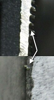
A burr is a raised edge or small piece of material that remains attached to a workpiece after a modification process.
A cutter location (CLData) refers to the position which a CNC milling machine has been instructed to hold a milling cutter by the instructions in the program.

A planer is a type of metalworking machine tool that uses linear relative motion between the workpiece and a single-point cutting tool to cut the work piece. A planer is similar to a shaper, but larger, and with workpiece moving, whereas in a shaper the cutting tool moves.

Tuckpointing is a way of using two contrasting colours of mortar in the mortar joints of brickwork, with one colour matching the bricks themselves to give an artificial impression that very fine joints have been made. In some parts of the United States and Canada, some confusion may result as the term is often used interchangeably with pointing and repointing.

Burnishing is the plastic deformation of a surface due to sliding contact with another object. It smooths the surface and makes it shinier. Burnishing may occur on any sliding surface if the contact stress locally exceeds the yield strength of the material. The phenomenon can occur both unintentionally as a failure mode, and intentionally as part of a manufacturing process. It is a squeezing operation under cold working.

A spotface or spot face is a machined feature in which a certain region of the workpiece is faced, providing a smooth, flat, accurately located surface. This is especially relevant on workpieces cast or forged, where the spotface's smooth, flat, accurately located surface stands in distinction to the surrounding surface whose roughness, flatness, and location are subject to wider tolerances and thus not assured with a machining level of precision. The most common application of spotfacing is facing the area around a bolt hole where the bolt's head will sit, which is often done by cutting a shallow counterbore, just deep enough "to clean up"—that is, only enough material is removed to get down past any irregularity and thus make the surface flat. Other common applications of spotfacing involve facing a pad onto a boss, creating planar surfaces in known locations that can orient a casting or forging into position in the assembly; allow part marking such as stamping or nameplate riveting; or offer machine-finish visual appeal in spots, without the need for finishing all over (FAO).
Threading is the process of creating a screw thread. More screw threads are produced each year than any other machine element. There are many methods of generating threads, including subtractive methods ; deformative or transformative methods ; additive methods ; or combinations thereof.
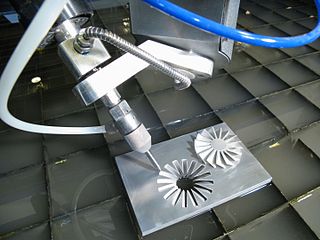
Multiaxis machining is a manufacturing process that involves tools that move in 4 or more directions and are used to manufacture parts out of metal or other materials by milling away excess material, by water jet cutting or by laser cutting. This type of machining was originally performed mechanically on large complex machines. These machines operated on 4, 5, 6, and even 12 axes which were controlled individually via levers that rested on cam plates. The cam plates offered the ability to control the tooling device, the table in which the part is secured, as well as rotating the tooling or part within the machine. Due to the machines size and complexity it took extensive amounts of time to set them up for production. Once computer numerically controlled machining was introduced it provided a faster, more efficient method for machining complex parts.

WorkNC is a Computer aided manufacturing (CAM) software developed by Sescoi for multi-axis machining.

Milling is the process of machining using rotary cutters to remove material by advancing a cutter into a workpiece. This may be done varying direction on one or several axes, cutter head speed, and pressure. Milling covers a wide variety of different operations and machines, on scales from small individual parts to large, heavy-duty gang milling operations. It is one of the most commonly used processes for machining custom parts to precise tolerances.

