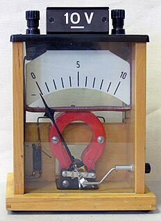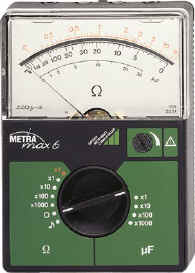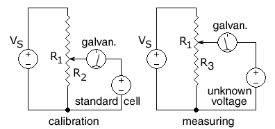
An ammeter /ˈamɪtə/ is a measuring instrument used to measure the current in a circuit. Electric currents are measured in Amperes (A), hence the name. The ammeter is usually connected in series with the circuit in which the current is to be measured. An ammeter usually has low resistance so that it does not cause a significant voltage drop in the circuit being measured.

A resistor is a passive two-terminal electrical component that implements electrical resistance as a circuit element. In electronic circuits, resistors are used to reduce current flow, adjust signal levels, to divide voltages, bias active elements, and terminate transmission lines, among other uses. High-power resistors that can dissipate many watts of electrical power as heat may be used as part of motor controls, in power distribution systems, or as test loads for generators. Fixed resistors have resistances that only change slightly with temperature, time or operating voltage. Variable resistors can be used to adjust circuit elements, or as sensing devices for heat, light, humidity, force, or chemical activity.

A thermocouple is an electrical device consisting of two dissimilar electrical conductors forming an electrical junction. A thermocouple produces a temperature-dependent voltage as a result of the Seebeck effect, and this voltage can be interpreted to measure temperature. Thermocouples are widely used as temperature sensors.

Voltage, electric potential difference, electric pressure or electric tension is the difference in electric potential between two points, which is defined as the work needed per unit of charge to move a test charge between the two points. In the International System of Units, the derived unit for voltage is named volt. In SI units, work per unit charge is expressed as joules per coulomb, where 1 volt = 1 joule per 1 coulomb. The old SI definition for volt used power and current; starting in 1990, the quantum Hall and Josephson effect were used, and recently (2019) fundamental physical constants have been introduced for the definition of all SI units and derived units. Voltage or electric potential difference is denoted symbolically by , simplified V, or U, for instance in the context of Ohm's or Kirchhoff's circuit laws.

A voltmeter is an instrument used for measuring electric potential difference between two points in an electric circuit. It is connected in parallel. It usually has a high resistance so that it takes negligible current from the circuit.

A Wheatstone bridge is an electrical circuit used to measure an unknown electrical resistance by balancing two legs of a bridge circuit, one leg of which includes the unknown component. The primary benefit of the circuit is its ability to provide extremely accurate measurements. Its operation is similar to the original potentiometer.

A galvanometer is an electromechanical measuring instrument for electric current. Early galvanometers were uncalibrated, but improved versions, called ammeters, were calibrated and could measure the flow of current more precisely.

An ohmmeter is an electrical instrument that measures electrical resistance. Multimeters also function as ohmmeters when in resistance-measuring mode.

A multimeter is a measuring instrument that can measure multiple electrical properties. A typical multimeter can measure voltage, resistance, and current, in which case it is also known as a volt-ohm-milliammeter (VOM), as the unit is equipped with voltmeter, ammeter, and ohmmeter functionality. Some feature the measurement of additional properties such as temperature and volume.

In electromagnetism and electronics, electromotive force is the electrical action produced by a non-electrical source. Devices provide an emf by converting other forms of energy into electrical energy, such as batteries or generators. Sometimes an analogy to water pressure is used to describe electromotive force..

A potentiometer is a three-terminal resistor with a sliding or rotating contact that forms an adjustable voltage divider. If only two terminals are used, one end and the wiper, it acts as a variable resistor or rheostat.
A transducer is a device that converts energy from one form to another. Usually a transducer converts a signal in one form of energy to a signal in another.

In electronics, a voltage divider is a passive linear circuit that produces an output voltage (Vout) that is a fraction of its input voltage (Vin). Voltage division is the result of distributing the input voltage among the components of the divider. A simple example of a voltage divider is two resistors connected in series, with the input voltage applied across the resistor pair and the output voltage emerging from the connection between them.
Resistance thermometers, also called resistance temperature detectors (RTDs), are sensors used to measure temperature. Many RTD elements consist of a length of fine wire wrapped around a ceramic or glass core but other constructions are also used. The RTD wire is a pure material, typically platinum, nickel, or copper. The material has an accurate resistance/temperature relationship which is used to provide an indication of temperature. As RTD elements are fragile, they are often housed in protective probes.
A load cell is a force transducer. It converts a force such as tension, compression, pressure, or torque into an electrical signal that can be measured and standardized. As the force applied to the load cell increases, the electrical signal changes proportionally. The most common types of load cell used are strain gauges, pneumatic, and hydraulic.
A Kelvin bridge, also called a Kelvin double bridge and in some countries a Thomson bridge, is a measuring instrument used to measure unknown electrical resistors below 1 ohm. It is specifically designed to measure resistors that are constructed as four terminal resistors.

An LCR meter is a type of electronic test equipment used to measure the inductance (L), capacitance (C), and resistance (R) of an electronic component. In the simpler versions of this instrument the impedance was measured internally and converted for display to the corresponding capacitance or inductance value. Readings should be reasonably accurate if the capacitor or inductor device under test does not have a significant resistive component of impedance. More advanced designs measure true inductance or capacitance, as well as the equivalent series resistance of capacitors and the Q factor of inductive components.

A Megohmmeter or insulation resistance tester is a special type of ohmmeter used to measure the electrical resistance of insulators. Insulating components, for example cable jackets, must be tested for their insulation strength at the time of commissioning and as part of maintenance of high voltage electrical equipment and installations.
The Kelvin-Varley voltage divider, named after its inventors William Thomson, 1st Baron Kelvin and Cromwell Fleetwood Varley, is an electronic circuit used to generate an output voltage as a precision ratio of an input voltage, with several decades of resolution. In effect, the Kelvin–Varley divider is an electromechanical precision digital-to-analog converter.

A measuring instrument is a device to measure a physical quantity. In the physical sciences, quality assurance, and engineering, measurement is the activity of obtaining and comparing physical quantities of real-world objects and events. Established standard objects and events are used as units, and the process of measurement gives a number relating the item under study and the referenced unit of measurement. Measuring instruments, and formal test methods which define the instrument's use, are the means by which these relations of numbers are obtained. All measuring instruments are subject to varying degrees of instrument error and measurement uncertainty. These instruments may range from simple objects such as rulers and stopwatches to electron microscopes and particle accelerators. Virtual instrumentation is widely used in the development of modern measuring instruments.


