Preselector

Last updated

Circuit of a very simple preselector. For any one frequency, using a larger tuning coil results in a narrower bandwidth, i.e. greater rejection of out-of-tune signals. Preselector, Wiring diagram of a simple radio circuit.png
Circuit of a very simple preselector. For any one frequency, using a larger tuning coil results in a narrower bandwidth, i.e. greater rejection of out-of-tune signals.

A preselector is a name for an electronic device that connects between a radio antenna and a radio receiver. The preselector is a band-pass filter that blocks troublesome out-of-tune frequencies from passing through from the antenna into the radio receiver (or preamplifier) that otherwise would be directly connected to the antenna.

Contents

Purpose

A preselector improves the performance of nearly any receiver, but is especially helpful to receivers with broadband front-ends that are prone to overload, such as scanners and ordinary consumer-market shortwave and AM broadcast receivers. [lower-alpha 1]

Frequency response curves for a simple preselector with tuning capacitor setting of 10, 30, 100, or 300 pF Response curves for a radio receiver preselector.png
Frequency response curves for a simple preselector with tuning capacitor setting of 10, 30, 100, or 300 pF

A preselector typically is tuned to have a narrow bandwidth, centered on the receiver's operating frequency. The preselector passes through the signal on the frequency it is tuned to unchanged (or only slightly diminished) but it reduces or removes off-frequency signals, cutting down or eliminating unwanted interference. [lower-alpha 2]

Extra filtering can be useful because the first input stage ("front end") of receivers contains at least one RF amplifier, which has power limits ("dynamic range"). Most radios' front ends amplify all radio frequencies delivered to the antenna connection. So off-frequency signals constitute a load on the RF amplifier, wasting part of its dynamic range on unwanted signals. "Limited dynamic range" means that the amplifier circuits have a limit to the total amount of incoming RF signal they can amplify without overloading, symptoms of which are nonlinearity ("distortion") and ultimately clipping ("buzz").

When the front-end overloads, the performance of the receiver is severely reduced, and in extreme cases can damage the receiver. [1] In situations with noisy and crowded bands, or where there are strong local stations, the dynamic range of the receiver can quickly be exceeded. Extra filtering by the preselector limits frequency range and power demands that are applied to all later stages of the receiver, only loading it with signals within the preselected band.

Multifunction preselectors

A preselector can be engineered so that in addition to attenuating interference from unwanted frequencies, it will perform other services which may be helpful for a receiver: It can limit input signal voltage to protect a sensitive receiver from damage caused by static discharge, nearby voltage spikes, and overload from nearby transmitters' signals; it can provide a DC path to ground, to drain off noisy static charge from building up on the antenna; it can also incorporate a small radio frequency amplifier stage to boost the filtered signal. None of these extra conveniences are necessary for the function of preselection, and in particular, for typical use an amplifier in the preselector serves no helpful purpose.

Antenna preamplifiers (preamps) can be made "tunable" by incorporating a front-end preselector circuit to improve their performance. The integrated device is both a preamplifier and a preselector, and either name is correct. This ambiguity sometimes leads to confusion – conflating preselection with amplification.

A regular, ordinary, standard preselector is sometimes called a "passive" preselector to emphasize that it has no internal amplifier and requires no power supply. Ordinary "passive" preselectors typically work well with modern receivers, with no noticeable signal loss.

Preselect filter bank

Spectrum analyzers and some wideband software-defined radio receivers incorporate a bank of switchable preselectors to reject out-of-band signals that could result in spurious signals at the frequencies being analyzed. In the case of software-defined radio receivers, many of which have limited dynamic range, a preselect filter bank also serves to limit strong out-of-band signals that could potentially saturate the receiver front-end. [2]

Bandwidth vs. signal strength trade-off

With all preselectors there is some very small loss at the tuned frequency; usually, most of the loss is in the inductor (the tuning coil). Turning up the inductance gives the preselector a narrower bandwidth (or higher Q, or greater selectivity) and slightly raises the loss, which nonetheless remains small.

Most preselectors have separate settings for one inductor and one capacitor (at least). [lower-alpha 3] So with at least two adjustments available to tune to just one frequency, there are often a variety of possible settings that will tune the preselector to frequencies in its middle-range.

For the narrowest bandwidth (highest Q), the preselector is tuned using the highest inductance and lowest capacitance for the desired frequency, but this produces the greatest loss. It also requires retuning the preselector more often while searching for faint signals, to keep the preselector's pass-through frequency adequately close to the radio's receiving frequency.

For lowest loss (and widest bandwidth), the preselector is tuned using the lowest inductance and highest capacitance (and the lowest Q, or least selectivity) for the desired frequency. The wider bandwidth allows more interference through from nearby frequencies, but reduces the need to retune the preselector while tuning the receiver, since any one low-inductance setting for the preselector will pass a wide span of nearby frequencies.

Different from an antenna tuner

Although a preselector is placed inbetween the radio and the antenna, in the same electrical location as a feedline matching unit, it serves a different purpose: A transmatch or “antenna” tuner connects two transmission lines with different impedances and only blocks out-of-tune frequencies incidentally (if it blocks any at all).

A transmatch matches transmitter impedance to feedline impedance and phase, so that signal power from the radio transmitter smoothly transfers into the antenna's feed cable; a properly adjusted transmatch prevents transmitted power from being reflected back into the transmitter (“backlash current”). Some antenna tuner circuits can both impedance match and preselect, [3] for example the Series Parallel Capacitor (SPC) tuner, and many ‘tuned-transformer’-type matching circuits used in many balanced line tuners (BLT) can be adjusted to also function as band-pass filters. [lower-alpha 4]

See also

Footnotes

  1. A preselector provides little or no benefit to receivers or preamps when they are fed from a narrow-band source, such as a tuned small loop antenna.
  2. Note that a preselector cannot remove any interference that comes through on the same frequency that it and the receiver are both tuned to.
  3. The setting dials may be labeled as "BAND" (inductor, possibly also selection of a capacitor bank) and "TUNE" (capacitor, or extra capacitance for fine-tuning). Regardless of the labeling, if more than one setting of the two is possible for the same frequency, the settings' bandwidths will differ along with other properties like output and input impedances.
  4. Some simpler types of antenna tuners that are not band-pass circuits can also provide limited preselection. The now-common C L C-type ‘T’‑network is a high-pass circuit which always essentially eliminates frequencies below the operating frequency, but even when adjusted for greatest selectivity, cannot block higher frequencies nearly as well as a conventional preselector. [4] It can, however, be adjusted for high operating Q that might attenuate noise above the operating frequency by as much as 20  dB. [5] The complementary π-network that was customarily incorporated in the final stage of ‘vintage’ tube transmitters and amplifiers is a low-pass circuit; it always essentially eliminates frequencies above the tuned frequency, and can be similarly adjusted to provide attenuation below the tuned frequency by as much as 20  dB. [5]

Related Research Articles

<span class="mw-page-title-main">Amplifier</span> Electronic device/component that increases the strength of a signal

An amplifier, electronic amplifier or (informally) amp is an electronic device that can increase the magnitude of a signal. It is a two-port electronic circuit that uses electric power from a power supply to increase the amplitude of a signal applied to its input terminals, producing a proportionally greater amplitude signal at its output. The amount of amplification provided by an amplifier is measured by its gain: the ratio of output voltage, current, or power to input. An amplifier is defined as a circuit that has a power gain greater than one.

<span class="mw-page-title-main">Superheterodyne receiver</span> Type of radio receiver

A superheterodyne receiver, often shortened to superhet, is a type of radio receiver that uses frequency mixing to convert a received signal to a fixed intermediate frequency (IF) which can be more conveniently processed than the original carrier frequency. It was long believed to have been invented by US engineer Edwin Armstrong, but after some controversy the earliest patent for the invention is now credited to French radio engineer and radio manufacturer Lucien Lévy. Virtually all modern radio receivers use the superheterodyne principle.

<span class="mw-page-title-main">Antenna (radio)</span> Electrical device

In radio engineering, an antenna or aerial is the interface between radio waves propagating through space and electric currents moving in metal conductors, used with a transmitter or receiver. In transmission, a radio transmitter supplies an electric current to the antenna's terminals, and the antenna radiates the energy from the current as electromagnetic waves. In reception, an antenna intercepts some of the power of a radio wave in order to produce an electric current at its terminals, that is applied to a receiver to be amplified. Antennas are essential components of all radio equipment.

<span class="mw-page-title-main">Varicap</span> Type of diode

In electronics, a varicap diode, varactor diode, variable capacitance diode, variable reactance diode or tuning diode is a type of diode designed to exploit the voltage-dependent capacitance of a reverse-biased p–n junction.

<span class="mw-page-title-main">Impedance matching</span> Matching loads to power sources in engineering

In electronics, impedance matching is the practice of designing or adjusting the input impedance or output impedance of an electrical device for a desired value. Often, the desired value is selected to maximize power transfer or minimize signal reflection. For example, impedance matching typically is used to improve power transfer from a radio transmitter via the interconnecting transmission line to the antenna. Signals on a transmission line will be transmitted without reflections if the transmission line is terminated with a matching impedance.

A variable frequency oscillator (VFO) in electronics is an oscillator whose frequency can be tuned over some range. It is a necessary component in any tunable radio transmitter and in receivers that works by the superheterodyne principle. The oscillator controls the frequency to which the apparatus is tuned.

<span class="mw-page-title-main">Tuned radio frequency receiver</span>

A tuned radio frequency receiver is a type of radio receiver that is composed of one or more tuned radio frequency (RF) amplifier stages followed by a detector (demodulator) circuit to extract the audio signal and usually an audio frequency amplifier. This type of receiver was popular in the 1920s. Early examples could be tedious to operate because when tuning in a station each stage had to be individually adjusted to the station's frequency, but later models had ganged tuning, the tuning mechanisms of all stages being linked together, and operated by just one control knob. By the mid 1930s, it was replaced by the superheterodyne receiver patented by Edwin Armstrong.

<span class="mw-page-title-main">Radio receiver</span> Device for receiving radio broadcasts

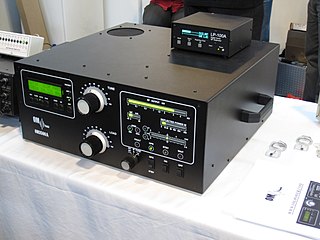
In radio communications, a radio receiver, also known as a receiver, a wireless, or simply a radio, is an electronic device that receives radio waves and converts the information carried by them to a usable form. It is used with an antenna. The antenna intercepts radio waves and converts them to tiny alternating currents which are applied to the receiver, and the receiver extracts the desired information. The receiver uses electronic filters to separate the desired radio frequency signal from all the other signals picked up by the antenna, an electronic amplifier to increase the power of the signal for further processing, and finally recovers the desired information through demodulation.

<span class="mw-page-title-main">Antenna tuner</span> Telecommunications device

An antenna tuner is an electronic device inserted into the feedline between a radio transmitter and its antenna. Its purpose is to optimize power transfer by matching the impedance of the radio to the impedance of the end of the feedline connecting the antenna to the transmitter.

<span class="mw-page-title-main">Tuner (radio)</span>

A tuner is a subsystem that receives radio frequency (RF) transmissions, such as FM broadcasting, and converts the selected carrier frequency and its associated bandwidth into a fixed frequency that is suitable for further processing, usually because a lower frequency is used on the output. Broadcast FM/AM transmissions usually feed this intermediate frequency (IF) directly into a demodulator that converts the radio signal into audio-frequency signals that can be fed into an amplifier to drive a loudspeaker.

<span class="mw-page-title-main">Electronic filter</span> Electronic device

Electronic filters are a type of signal processing filter in the form of electrical circuits. This article covers those filters consisting of lumped electronic components, as opposed to distributed-element filters. That is, using components and interconnections that, in analysis, can be considered to exist at a single point. These components can be in discrete packages or part of an integrated circuit.

<span class="mw-page-title-main">Variable capacitor</span> Capacitor whose capacitance can be changed

A variable capacitor is a capacitor whose capacitance may be intentionally and repeatedly changed mechanically or electronically. Variable capacitors are often used in L/C circuits to set the resonance frequency, e.g. to tune a radio, or as a variable reactance, e.g. for impedance matching in antenna tuners.

<span class="mw-page-title-main">Braid-breaker</span>

A braid-breaker is a filter that prevents television interference (TVI). In many cases, TVI is caused by a high field strength of a nearby high frequency (HF) transmitter, the aerial down lead plugged into the back of the TV acts as a longwire antenna or as a simple vertical element. The radio frequency (RF) current flowing through the tuner of the TV tends to generate harmonics which then spoil the viewing.

A radio transmitter or just transmitter is an electronic device which produces radio waves with an antenna. Radio waves are electromagnetic waves with frequencies between about 30 Hz and 300 GHz. The transmitter itself generates a radio frequency alternating current, which is applied to the antenna. When excited by this alternating current, the antenna radiates radio waves. Transmitters are necessary parts of all systems that use radio: radio and television broadcasting, cell phones, wireless networks, radar, two way radios like walkie talkies, radio navigation systems like GPS, remote entry systems, among numerous other uses.

In electronics, motorboating is a type of low frequency parasitic oscillation that sometimes occurs in audio and radio equipment and often manifests itself as a sound similar to an idling motorboat engine, a "put-put-put", in audio output from speakers or earphones. It is a problem encountered particularly in radio transceivers and older vacuum tube audio systems, guitar amplifiers, PA systems and is caused by some type of unwanted feedback in the circuit. The amplifying devices in audio and radio equipment are vulnerable to a variety of feedback problems, which can cause distinctive noise in the output. The term motorboating is applied to oscillations whose frequency is below the range of hearing, from 1 to 10 hertz, so the individual oscillations are heard as pulses. Sometimes the oscillations can even be seen visually as the woofer cones in speakers slowly moving in and out.

A radio transmitter or receiver is connected to an antenna which emits or receives the radio waves. The antenna feed system or antenna feed is the cable or conductor, and other associated equipment, which connects the transmitter or receiver with the antenna and makes the two devices compatible. In a radio transmitter, the transmitter generates an alternating current of radio frequency, and the feed system feeds the current to the antenna, which converts the power in the current to radio waves. In a radio receiver, the incoming radio waves excite tiny alternating currents in the antenna, and the feed system delivers this current to the receiver, which processes the signal.

<span class="mw-page-title-main">Valve RF amplifier</span> Device for electrically amplifying the power of an electrical radio frequency signal

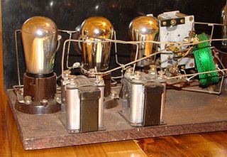
A valve RF amplifier or tube amplifier (U.S.) is a device for electrically amplifying the power of an electrical radio frequency signal.

<span class="mw-page-title-main">Transformer types</span> Overview of electrical transformer types

A variety of types of electrical transformer are made for different purposes. Despite their design differences, the various types employ the same basic principle as discovered in 1831 by Michael Faraday, and share several key functional parts.

Radio-frequency (RF) engineering is a subset of electronic engineering involving the application of transmission line, waveguide, antenna and electromagnetic field principles to the design and application of devices that produce or use signals within the radio band, the frequency range of about 20 kHz up to 300 GHz.

<span class="mw-page-title-main">Yaesu FT-817</span>

The Yaesu FT-817 is one of the smallest MF/HF/VHF/UHF multimode general-coverage amateur radio transceivers. The set is built by the Japanese Vertex Standard Corporation and is sold under the Yaesu brand. With internal battery pack, on board keyer, its all mode/all band capability and flexible antenna, the set is particularly well suited for portable use. The FT-817 is based on a similar circuit architecture as Yaesu's FT-857 and FT-897, so it is a compromise transceiver and incorporates its features to its low price.

References

  1. Cutsogeorge, George (2014) [2009]. Managing Interstation Interference with Coaxial Stubs and Filters (2nd ed.). Aptos, CA: International Radio Corporation.
  2. "A primer on RF filters for software-defined radio". Software-Defined Radio Simplified (blog). 24 February 2020. Retrieved 17 April 2022.
  3. Stanley, John (K4ERO) (1999). "The filtuner". ARRL Antenna Compendium. Vol. 6. Newington, CT: American Radio Relay League.
  4. Griffith, Andrew S. (W4ULD) (January 1995). "Getting the most out of your 'T'‑network antenna tuner". QST Magazine Magazine. Newington, CT: American Radio Relay League. pp. 44–47. ISSN   0033-4812. OCLC   1623841.
  5. 1 2 Stanley, John, K4ERO (September 2015). "Antenna tuners as preselectors". Technical Correspondence. QST Magazine . Newington, CT: American Radio Relay League. p. 61.{{cite magazine}}: CS1 maint: multiple names: authors list (link)