
An inductor, also called a coil, choke, or reactor, is a passive two-terminal electrical component that stores energy in a magnetic field when electric current flows through it. An inductor typically consists of an insulated wire wound into a coil around a core.
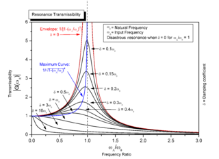
Resonance describes the phenomenon of increased amplitude that occurs when the frequency of a periodically applied force is equal or close to a natural frequency of the system on which it acts. When an oscillating force is applied at a resonant frequency of a dynamical system, the system will oscillate at a higher amplitude than when the same force is applied at other, non-resonant frequencies.

In electrical engineering, electrical impedance is the measure of the opposition that a circuit presents to a current when a voltage is applied.

In physics and engineering the quality factor or Q factor is a dimensionless parameter that describes how underdamped an oscillator or resonator is. It is defined as the ratio of the peak energy stored in the resonator in a cycle of oscillation to the energy lost per radian of the cycle. Q factor is alternatively defined as the ratio of a resonator's centre frequency to its bandwidth when subject to an oscillating driving force. These two definitions give numerically similar, but not identical, results. Higher Q indicates a lower rate of energy loss and the oscillations die out more slowly. A pendulum suspended from a high-quality bearing, oscillating in air, has a high Q, while a pendulum immersed in oil has a low one. Resonators with high quality factors have low damping, so that they ring or vibrate longer.
A resistor–capacitor circuit, or RC filter or RC network, is an electric circuit composed of resistors and capacitors driven by a voltage or current source. A first order RC circuit is composed of one resistor and one capacitor and is the simplest type of RC circuit.

In electronics, impedance matching is the practice of designing the input impedance of an electrical load or the output impedance of its corresponding signal source to maximize the power transfer or minimize signal reflection from the load. A source of electric power such as a generator, amplifier or radio transmitter has a source impedance which is equivalent to an electrical resistance in series with a reactance. An electrical load, such as a light bulb, transmission line or antenna similarly has an impedance which is equivalent to a resistance in series with a reactance. The maximum power theorem says that maximum power is transferred from source to load when the load resistance equals the source resistance and the load reactance equals the negative of the source reactance. Another way of saying this is that the load impedance must equal the complex conjugate of the source impedance. If this condition is met the two parts of the circuit are said to be impedance matched.

A gyrator is a passive, linear, lossless, two-port electrical network element proposed in 1948 by Bernard D. H. Tellegen as a hypothetical fifth linear element after the resistor, capacitor, inductor and ideal transformer. Unlike the four conventional elements, the gyrator is non-reciprocal. Gyrators permit network realizations of two-(or-more)-port devices which cannot be realized with just the conventional four elements. In particular, gyrators make possible network realizations of isolators and circulators. Gyrators do not however change the range of one-port devices that can be realized. Although the gyrator was conceived as a fifth linear element, its adoption makes both the ideal transformer and either the capacitor or inductor redundant. Thus the number of necessary linear elements is in fact reduced to three. Circuits that function as gyrators can be built with transistors and op-amps using feedback.

An LC circuit, also called a resonant circuit, tank circuit, or tuned circuit, is an electric circuit consisting of an inductor, represented by the letter L, and a capacitor, represented by the letter C, connected together. The circuit can act as an electrical resonator, an electrical analogue of a tuning fork, storing energy oscillating at the circuit's resonant frequency.
A Colpitts oscillator, invented in 1918 by American engineer Edwin H. Colpitts, is one of a number of designs for LC oscillators, electronic oscillators that use a combination of inductors (L) and capacitors (C) to produce an oscillation at a certain frequency. The distinguishing feature of the Colpitts oscillator is that the feedback for the active device is taken from a voltage divider made of two capacitors in series across the inductor.
A resistor–inductor circuit, or RL filter or RL network, is an electric circuit composed of resistors and inductors driven by a voltage or current source. A first-order RL circuit is composed of one resistor and one inductor and is the simplest type of RL circuit.

In microwave and radio-frequency engineering, a stub or resonant stub is a length of transmission line or waveguide that is connected at one end only. The free end of the stub is either left open-circuit, or short-circuited. Neglecting transmission line losses, the input impedance of the stub is purely reactive; either capacitive or inductive, depending on the electrical length of the stub, and on whether it is open or short circuit. Stubs may thus function as capacitors, inductors and resonant circuits at radio frequencies.

Electrical resonance occurs in an electric circuit at a particular resonant frequency when the impedances or admittances of circuit elements cancel each other. In some circuits, this happens when the impedance between the input and output of the circuit is almost zero and the transfer function is close to one.
Foster's reactance theorem is an important theorem in the fields of electrical network analysis and synthesis. The theorem states that the reactance of a passive, lossless two-terminal (one-port) network always strictly monotonically increases with frequency. It is easily seen that the reactances of inductors and capacitors individually increase with frequency and from that basis a proof for passive lossless networks generally can be constructed. The proof of the theorem was presented by Ronald Martin Foster in 1924, although the principle had been published earlier by Foster's colleagues at American Telephone & Telegraph.
Ripple in electronics is the residual periodic variation of the DC voltage within a power supply which has been derived from an alternating current (AC) source. This ripple is due to incomplete suppression of the alternating waveform after rectification. Ripple voltage originates as the output of a rectifier or from generation and commutation of DC power.

A capacitor is a device that stores electrical energy in an electric field. It is a passive electronic component with two terminals.

Zobel networks are a type of filter section based on the image-impedance design principle. They are named after Otto Zobel of Bell Labs, who published a much-referenced paper on image filters in 1923. The distinguishing feature of Zobel networks is that the input impedance is fixed in the design independently of the transfer function. This characteristic is achieved at the expense of a much higher component count compared to other types of filter sections. The impedance would normally be specified to be constant and purely resistive. For this reason, Zobel networks are also known as constant resistance networks. However, any impedance achievable with discrete components is possible.

A lattice phase equaliser or lattice filter is an example of an all-pass filter. That is, the attenuation of the filter is constant at all frequencies but the relative phase between input and output varies with frequency. The lattice filter topology has the particular property of being a constant-resistance network and for this reason is often used in combination with other constant resistance filters such as bridge-T equalisers. The topology of a lattice filter, also called an X-section is identical to bridge topology. The lattice phase equaliser was invented by Otto Zobel. using a filter topology proposed by George Campbell.

Prototype filters are electronic filter designs that are used as a template to produce a modified filter design for a particular application. They are an example of a nondimensionalised design from which the desired filter can be scaled or transformed. They are most often seen in regard to electronic filters and especially linear analogue passive filters. However, in principle, the method can be applied to any kind of linear filter or signal processing, including mechanical, acoustic and optical filters.

A microwave cavity or radio frequency (RF) cavity is a special type of resonator, consisting of a closed metal structure that confines electromagnetic fields in the microwave region of the spectrum. The structure is either hollow or filled with dielectric material. The microwaves bounce back and forth between the walls of the cavity. At the cavity's resonant frequencies they reinforce to form standing waves in the cavity. Therefore, the cavity functions similarly to an organ pipe or sound box in a musical instrument, oscillating preferentially at a series of frequencies, its resonant frequencies. Thus it can act as a bandpass filter, allowing microwaves of a particular frequency to pass while blocking microwaves at nearby frequencies.

An RLC circuit is an electrical circuit consisting of a resistor (R), an inductor (L), and a capacitor (C), connected in series or in parallel. The name of the circuit is derived from the letters that are used to denote the constituent components of this circuit, where the sequence of the components may vary from RLC.


