RIAA equalization

Last updated

The RIAA equalization curve for playback of vinyl records. The recording curve performs the inverse function, reducing low frequencies and boosting high frequencies. RIAA-EQ-Curve rec play.svg
The RIAA equalization curve for playback of vinyl records. The recording curve performs the inverse function, reducing low frequencies and boosting high frequencies.

RIAA equalization is a specification for the recording and playback of phonograph records, established by the Recording Industry Association of America (RIAA). The purposes of the equalization are to permit greater recording times (by decreasing the mean width of each groove), to improve sound quality, and to reduce the groove damage that would otherwise arise during playback.

Contents

The RIAA equalization curve was intended to operate as a de facto global industry standard for records since 1954, but when the change actually took place is difficult to determine. [1]

Before then, especially from 1940, each record company applied its own equalization; over 100 combinations of turnover and rolloff frequencies were in use, the main ones being Columbia-78, Decca-U.S., European (various), Victor-78 (various), Associated, BBC, NAB, Orthacoustic, World, Columbia LP, FFRR-78 and microgroove, and AES. The obvious consequence was that different reproduction results were obtained if the recording and playback filtering were not matched.

The RIAA curve

RIAA equalization is a form of pre-emphasis on recording and de-emphasis on playback. A recording is made with the low frequencies reduced and the high frequencies boosted, and on playback, the opposite occurs. The net result is a flat frequency response, but with attenuation of high-frequency noise such as hiss and clicks that arise from the recording medium. Reducing the low frequencies also limits the excursions the cutter needs to make when cutting a groove. Groove width is thus reduced, allowing more grooves to fit into a given surface area, permitting longer recording times. This also reduces physical stresses on the stylus, which might otherwise cause distortion or groove damage during playback.

A potential drawback of the system is that rumble from the playback turntable's drive mechanism is amplified by the low-frequency boost that occurs on playback. Players must, therefore, be designed to limit rumble, more so than if RIAA equalization did not occur.

RIAA playback equalization is not a simple low-pass filter. It defines transition points in three places: 75 μs, 318 μs and 3180 μs, which correspond to 2122 Hz, 500 Hz and 50 Hz (rounded values). [2] Mathematically, the pre-emphasis transfer function is expressed as follows, where T1=3180 μs, T2=318 μs, T3=75 μs: [3]

Implementing this characteristic is not especially difficult, but is more involved than a simple amplifier. [4] Practically every 20th century hi-fi preamplifier, integrated amplifier and receiver featured a built-in phono preamplifier with the RIAA characteristic. As more modern designs omitted the phonograph inputs, add-on phono preamplifiers with the RIAA equalization curve have become available. These adapt a magnetic phono cartridge to an unbalanced −10  dBv consumer line-level RCA input. Some modern turntables feature built-in preamplification to the RIAA standard. Special preamplifiers are also available for the various equalization curves used on pre-1954 records.

Digital audio editors often feature the ability to equalize audio samples using standard and custom equalization curves, removing the need for a dedicated hardware preamplifier when capturing audio with a computer. However, this can add an extra step in processing a sample, and may amplify or reduce audio quality deficiencies of the sound card being used to capture the signal.

History

Origins of pre-emphasis

Equalization practice for electrical recordings dates to the beginning of the art. In 1926, Joseph P. Maxwell and Henry C. Harrison from Bell Telephone Laboratories disclosed that the recording pattern of the Western Electric "rubber line" magnetic disc cutter had a constant-velocity characteristic. This meant that as frequency increased in the treble, recording amplitude decreased. Conversely in the bass, as frequency decreased, recording amplitude increased. Therefore, attenuating the bass frequencies was necessary below about 250  Hz, the bass turnover point, in the amplified microphone signal fed to the recording head. Otherwise, bass modulation became excessive and overcutting took place, with the cutter getting into the next record groove. When played back electrically with a magnetic pickup having a smooth response in the bass region, a complementary boost in amplitude at the bass turnover point was necessary. G. H. Miller in 1934 reported that when complementary boost at the turnover point was used in radio broadcasts of records, the reproduction was more realistic and many of the musical instruments stood out in their true form.

West in 1930 and later P. G. H. Voight (1940) showed that the early Wente-style condenser microphones contributed to a 4- to 6-dB midrange brilliance or pre-emphasis in the recording chain. This meant that the electrical recording characteristics of Western Electric licensees such as Columbia Records and Victor Talking Machine Company had a higher amplitude in the midrange region. Brilliance such as this compensated for dullness in many early magnetic pickups having drooping midrange and treble response. As a result, this practice was the empirical beginning of using pre-emphasis above 1,000 Hz in 78 and 3313 rpm records, some 29 years before the RIAA curve.

Over the years, a variety of record equalization practices emerged, with no industry standard. For example, in Europe, for many years recordings required playback with a bass turnover setting of 250 to 300 Hz and a treble rolloff at 10,000 Hz ranging from 0 to −5 dB, or more. In the United States, practices varied and a tendency arose to use higher bass turnover frequencies, such as 500 Hz, as well as a greater treble rolloff such as −8.5 dB, and more. The purpose was to record higher modulation levels on the record.

Standardization

Evidence from the early technical literature concerning electrical recording suggests that serious efforts to standardize recording characteristics within an industry did not occur until 1942–1949. Before this time, electrical recording technology from company to company was considered a proprietary art all the way back to the 1925 Western Electric licensed method first used by Columbia and Victor. For example, what Brunswick-Balke-Collender (Brunswick Corporation) did was different from the practices of Victor.

Broadcasters were faced with having to adapt daily to the varied recording characteristics of many sources - various makers of "home recordings" readily available to the public, European recordings, lateral cut transcriptions, and vertical cut transcriptions. Efforts were started in 1942 to standardize within the National Association of Broadcasters (NAB), later known as the National Association of Radio and Television Broadcasters. The NAB, among other items, issued recording standards in 1942 and 1949 for laterally and vertically cut records, principally transcriptions. A number of 78 rpm record producers, as well as early LP makers, also cut their records to the NAB lateral standard.

The lateral-cut NAB curve was remarkably similar to the NBC Orthacoustic curve, which evolved from practices within the National Broadcasting Company since the mid-1930s. Empirically, and not by any formula, the bass end of the audio spectrum below 100 Hz could be boosted somewhat to override system hum and turntable rumble noises. Likewise at the treble end beginning at 1,000 Hz, if audio frequencies were boosted by 16 dB at 10,000 Hz the delicate sibilant sounds of speech and high overtones of musical instruments could be heard despite the high background noise of shellac discs. When the record was played back using a complementary inverse curve (de-emphasis), signal-to-noise ratio was improved and the programming sounded more lifelike.

In a related area, around 1940 treble pre-emphasis similar to that used in the NBC Orthacoustic recording curve was first employed by Edwin Howard Armstrong in his system of frequency modulation (FM) radio broadcasting. FM radio receivers using Armstrong circuits and treble de-emphasis would render high-quality, wide-range audio output with low noise levels.

When the Columbia LP was released in June 1948, the developers subsequently published technical information about the 3313 rpm, microgroove, long-playing record. [5] Columbia disclosed a recording characteristic showing that it was like the NAB curve in the treble, but had more bass boost or pre-emphasis below about 150 Hz. The authors disclosed electrical network characteristics for the Columbia LP curve. Nevertheless, the curve was not yet based on mathematical formulae, at least not explicitly.

In 1951, at the beginning of the post-World War II high fidelity (hi-fi) popularity, the Audio Engineering Society (AES) developed a standard playback curve. [6] This was intended for use by hi-fi amplifier manufacturers. If records were engineered to sound good on hi-fi amplifiers using the AES curve, this would be a worthy goal towards standardization. This curve was defined by the transition frequencies of audio filters and had a pole at 2.5 kHz (approximately 63.7 μs) and a zero at 400 Hz (approximately 397.9 μs).

RCA Victor and Columbia were in a "market war" concerning which recorded format was going to win: the Columbia LP versus the RCA Victor 45 rpm disc (released in February 1949). Besides also being a battle of disc size and record speed, there was a technical difference in the recording characteristics. RCA Victor was using "New Orthophonic", whereas Columbia was using their own LP curve.

Ultimately, the New Orthophonic curve was disclosed in a publication by R. C. Moyer of RCA Victor in 1953; [7] additional background information about this evolution can also be found in another article of the same author, published in 1957. [8] He traced the RCA Victor characteristics back to the Western Electric "rubber line" recorder in 1925 up to the early 1950s laying claim to long-held recording practices and reasons for major changes in the intervening years. The RCA Victor New Orthophonic curve was within the tolerances for the NAB/NARTB, Columbia LP, and AES curves. It eventually became the technical predecessor to the RIAA curve.

Between 1953 and 1956 (before the stereo LP in 1958), several standards bodies around the world adopted the same playback curve—identical to the RCA Victor New Orthophonic curve—which became standard throughout the national and international record markets. [9] However, although these standards were all identical, no universal name was used. One of the standards was called simply "RIAA", and it is likely that this name was eventually adopted because it was memorable.

Some niche record cutters possibly were still using EQ curves other than the RIAA curve well into the 1970s. As a result, some audio manufacturers today produce phono equalizers with selectable EQ curves, including options for Columbia LP, Decca, CCIR, and TELDEC's Direct Metal Mastering.

The Mythical 'Neumann pole'

The official RIAA standard defines three time-constants with pre-emphasis rising indefinitely above 75 μs, but in practice this is not possible. When the RIAA equalization standard was written the inherent bandwidth limitations of the recording equipment and cutting amplifier imposed their own ultimate upper limit on the pre-emphasis characteristic, so no official upper limit was included in the RIAA definition.

Modern systems have far wider potential bandwidth. An essential feature of all cutting amplifiers—including the Neumann cutting amplifiers—is a forcibly imposed high frequency roll-off above the audio band (>20 kHz). This implies two or more additional time constants to those defined by the RIAA curve. This is not standardized anywhere, but set by the maker of the cutting amplifier and associated electronics.

The so-called 'Neumann pole' attempts to provide complementary correction for these unofficial time constants upon playback. However, there is no such pole.

Background

In 1995, an unqualified source erroneously suggested that Neumann cutting amplifiers applied a single high-frequency zero at 3.18 μs (about 50 kHz) and that a complementary zero should therefore be included upon playback. [10] However, no such zero exists. [11] [2]

For example, the RIAA pre-emphasis in the popular Neumann SAB 74B equalizer applies a second-order roll off at 49.9 kHz, implemented by a Butterworth (maximally flat) active filter, plus an additional pole at 482 kHz. [2] This cannot be compensated for by a simple zero even if it were necessary, and in any case, other amplifiers will differ. Correction upon playback is not, in fact, required, as it is taken into account at the cutting stage when manual equalization is applied while monitoring initial cuts on a standard RIAA playback system. Nevertheless, the use of the erroneous zero, misnamed 'pole', remains a subject of some debate among amateur enthusiasts.

Many common phono preamplifier designs using negative feedback equalization include an unintentional zero at high frequencies, caused by using series negative feedback around a non-inverting gain stage, which cannot reduce the gain below 1. This was noted in the Lipshitz JAES paper, [4] as t6, with equations and RC networks for a solution: all of which was missed by Wright, who claimed it was not mentioned by Lipshitz. This solution is implemented in some but not all affected phono preamplifiers. [11]

IEC RIAA curve

In 1976, an alternative version of the replay curve (but not the recording curve) was proposed by the International Electrotechnical Commission, differing from the RIAA replay curve only in the addition of a pole at 7950 μs (approximately 20 Hz). [12] The justification was to reduce the subsonic output of the phono amplifier caused by disk warp and turntable rumble.

This so-called IEC amendment to the RIAA curve is not universally seen as desirable, as it introduces considerable amplitude and—of more concern—phase errors into the low-frequency response during playback. The simple first-order roll-off also provides only very mild reduction of rumble, [11] and many manufacturers consider that turntables, arm, and cartridge combinations should be of sufficient quality for problems not to arise.

Some manufacturers follow the IEC standard, others do not, while the remainder make this IEC-RIAA option user selectable. It remains subject to debate some 35 years later. [2] This IEC Amendment was withdrawn in June 2009, though.

TELDEC/DIN Curve

Telefunken and Decca founded a record company (Teldec) that used a characteristic which was also proposed for German DIN Standards in July 1957 (Entwurf DIN 45533, DIN 45536, and DIN 45537). Incidentally, this Standards proposal defined exactly the same characteristic as the intermediate CCIR Recommendation No. 208 of 1956, which was valid until about mid 1959. Nevertheless, the DIN Standards proposal was adopted in April 1959 (DIN 45533:1959, DIN 45536:1959, and DIN 45537:1959), that is, at a time when the RIAA characteristic was already well-established; and it was in effect until November 1962, when the German DIN finally adopted the RIAA characteristic (DIN 45536:1962 and DIN 45537:1962). The extent of usage of the Teldec characteristic is unclear, though.

The time constants of the Teldec characteristic are 3180 μs (approximately 50 Hz), 318 μs (approximately 500 Hz), and 50 μs (approximately 3183 Hz), thus differing only in the third value from the corresponding RIAA values. [13] Although the Teldec characteristic is close to the RIAA characteristic, it is different enough for recordings recorded with the former and played back with the latter to sound a little dull. [14]

Related Research Articles

<span class="mw-page-title-main">High fidelity</span> High-quality reproduction of sound

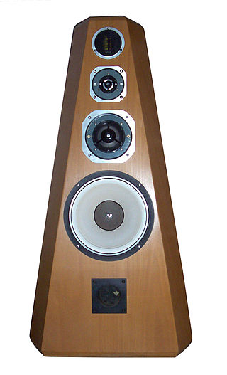
High fidelity is the high-quality reproduction of sound. It is popular with audiophiles and home audio enthusiasts. Ideally, high-fidelity equipment has inaudible noise and distortion, and a flat frequency response within the human hearing range.

<span class="mw-page-title-main">Emphasis (telecommunications)</span> Process of boosting noise-prone parts of the signal before transmission (and reversing upon receipt)

In signal processing, pre-emphasis is a technique to protect against anticipated noise. The idea is to boost the frequency range that is most susceptible to noise beforehand, so that after a noisy process more information can be recovered from that frequency range. Removal of the distortion caused by pre-emphasis is called de-emphasis, making the output accurately reproduce the original input.

<span class="mw-page-title-main">Audiophile</span> High-fidelity sound reproduction enthusiast

An audiophile is a person who is enthusiastic about high-fidelity sound reproduction. An audiophile seeks to reproduce recorded music to achieve high sound quality, typically in a quiet listening space and in a room with good acoustics.

<span class="mw-page-title-main">RCA connector</span> Electrical connector used for analog audio and video

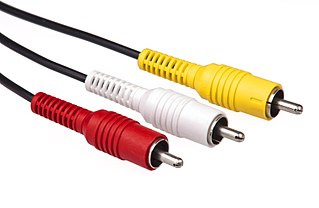
The RCA connector is a type of electrical connector commonly used to carry audio and video signals. The name RCA derives from the company Radio Corporation of America, which introduced the design in the 1930s. The connector’s male plug and female jack are called RCA plug and RCA jack.

A cassette deck is a type of tape machine for playing and recording audio cassettes that does not have a built-in power amplifier or speakers, and serves primarily as a transport. It can be a part of an automotive entertainment system, a part of a portable mini system or a part of a home component system. In the latter case it is also called a component cassette deck or just a component deck.

<span class="mw-page-title-main">Phonograph record</span> Disc-shaped analog sound storage medium

A phonograph record, a vinyl record, or simply a record or vinyl is an analog sound storage medium in the form of a flat disc with an inscribed, modulated spiral groove. The groove usually starts near the periphery and ends near the center of the disc. For about half a century, the discs were commonly made from shellac, with earlier records having a fine abrasive filler mixed in. Starting in the 1940s, polyvinyl chloride (PVC) became common, the "vinyl records" of the late 20th century.

<span class="mw-page-title-main">DIN connector</span> Electrical connector

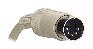
The DIN connector is an electrical connector that was standardized by the Deutsches Institut für Normung (DIN), the German Institute for Standards, in the mid 1950's, initial with 3 pins for mono, but when stereo connections and gear appeared in late 1950's, versions with 5 pins or more were launched. The male DIN connectors (plugs) feature a 13.2 mm diameter metal shield with a notch that limits the orientation in which plug and socket can mate. The range of DIN connectors, different only in the configuration of the pins, have been standardized as DIN 41524 / IEC/DIN EN 60130-9 ; DIN 45322 ; DIN 45329 / IEC/DIN EN 60130–9 ; and DIN 45326 / IEC/DIN EN 60130-9.

PS Audio is an American company specializing in high-fidelity audio components equipment for audiophiles and the sound recording industry. It currently produces audio amplifiers, preamplifiers, power related products, digital-to-analog converters, streaming audio, music management software and cables.

Tone control is a type of equalization used to make specific pitches or frequencies in an audio signal softer or louder. It allows a listener to adjust the tone of the sound produced by an audio system to their liking, for example to compensate for inadequate bass response of loudspeakers or earphones, tonal qualities of the room, or hearing impairment. A tone control circuit is an electronic circuit that consists of a network of filters which modify the signal before it is fed to speakers, headphones or recording devices by way of an amplifier. Tone controls are found on many sound systems: radios, portable music players, boomboxes, public address systems, and musical instrument amplifiers.

<span class="mw-page-title-main">AV receiver</span> Consumer electronics component

An audio/video receiver (AVR) is a consumer electronics component used in a home theater. Its purpose is to receive audio and video signals from a number of sources, and to process them and provide power amplifiers to drive loudspeakers and route the video to displays such as a television, monitor or video projector. Inputs may come from a satellite receiver, radio, DVD players, Blu-ray Disc players, VCRs or video game consoles, among others. The AVR source selection and settings such as volume, are typically set by a remote controller.

Dynagroove is a recording process introduced in 1963 by RCA Victor that, for the first time, used analog computers to modify the audio signal used to produce master discs for LPs. The intent was to boost bass on quiet passages, and reduce the high-frequency tracing burdens (distortion) for the less-compliant, "ball" or spherical-tipped playback cartridges then in use. With boosted bass, tracing demands could be reduced in part by reduced recording levels, sometimes supplemented by peak compression. This added top-end margin permitted selective pre-emphasis of some passages for greater perceived (psychological) brilliance of the recording as a whole. As with any compander, the program material itself changed the response of the Dynagroove electronics that processed it. But, because the changes were multiple and algorithmic, RCA justifiably referred to the analog device as a computer.

Phono input is a set of input jacks, usually mini jacks or RCA connectors, located on the rear panel of a preamp, mixer or amplifier, especially on early radio sets, to which a phonograph or turntable is attached.

Record restoration, a particular kind of audio restoration, is the process of converting the analog signal stored on gramophone records into digital audio files that can then be edited with computer software and eventually stored on a hard-drive, recorded to digital tape, or burned to a CD or DVD. The process may be divided into several separate steps performed in the following order:

  1. Cleaning the record, to prevent unwanted audio artifacts from being introduced in the capture that will necessitate correction in the digital domain, and to prevent unnecessary wear and damage to the stylus used in playback.
  2. Transcription of the record to another format on another medium ;
  3. Processing the raw sound file with software in order to remove transient noise resulting from record surface damage ;
  4. Using software to adjust the volume and equalization;
  5. Processing the audio with digital and analogue techniques to reduce surface/wideband noise;
  6. Saving the file in the desired format.

The AES coarse-groove calibration discs (AES-S001-064) are a boxed set of two identical discs, one for routine use, one for master reference. The intent is to characterize the reproduction chain for the mass transfer of coarse-groove records to digital media, much like using a photographic calibration reference in image work.

A smiley face curve or mid scoop in audio signal processing is a target frequency response curve characterized by boosted low and high frequencies coupled with reduced midrange frequency power. This curve is often attained by users employing a graphic equalizer, which shows a graphic representation of a "smile" using its frequency band faders to form a curve that sweeps upwards at each end of the frequency spectrum. Smiley face curves have been popular with some car audio enthusiasts, disc jockeys, electric bass players, home stereo owners and sound reinforcement operators. Though the graphic equalizer was intended to tailor a system's response to compensate for venue and performance conditions, the smiley face curve is sometimes applied as a purely stylistic effect.

<span class="mw-page-title-main">Nikko TRM-800</span> Stereo audio amplifier

The TRM-800 was a high-end solid state integrated stereo amplifier made in Japan, using NEC power transistors, by Nikko. It was the top-of-the-line model in the Nikko amplifier range of TRM's series; housed in a wooden walnut-finished cabinet and a brushed aluminum front panel, was introduced in 1975 the same year as the Marantz 2235. It was a two-channel amp; however, it had three sets of speaker connections; those powered selected by buttons. At 8 ohms, the amp could put out 65 Watts per channel RMS, delivering superb high fidelity sound with exceptional tone quality. Unlike many amps of this time, however, the TRM-800 was stable at lower impedances than 8 ohms; down to 4 ohms. The TRM-800's frequency response ranges 10Hz to 40.000 Hz ±1 dB with T.H.D. less than 0.1% at rated output. Its preamplifier and main amplifier were separable for multi-channel amplifier systems. The amp has internal circuit breakers which prevent it from clipping or overheating. Its power consumption is 250 watts. For equalization it has only a bass and a treble knob; however the frequency of these are selectable; between 250 and 500 Hertz for the bass, and between 2.5 and 5 kHz for the treble. It also has a high, low, and a subsonic filter. There are two phono stages; phono 2 is provided with impedance matching selection, for using different types of cartridges (MC/MM).

<span class="mw-page-title-main">Equalization (audio)</span> Changing the balance of frequency components in an audio signal

Equalization, or simply EQ, in sound recording and reproduction is the process of adjusting the volume of different frequency bands within an audio signal. The circuit or equipment used to achieve this is called an equalizer.

<span class="mw-page-title-main">Compatible Discrete 4</span> Discrete 4-channel quadraphonic gramophone record format developed by JVC

Compatible Discrete 4, also known as Quadradisc or CD-4 was a discrete four-channel quadraphonic system for phonograph records. The system was created by JVC and RCA in 1971 and introduced in May 1972. Hundreds of recordings using this technology were released on LP during the 1970s.

<span class="mw-page-title-main">Compact Cassette tape types and formulations</span>

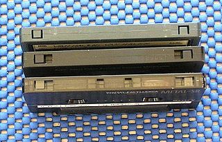
Audio compact cassettes use magnetic tape of three major types which differ in fundamental magnetic properties, the level of bias applied during recording, and the optimal time constant of replay equalization. Specifications of each type were set in 1979 by the International Electrotechnical Commission (IEC): Type I, Type II, Type III, and Type IV. 'Type 0' was a non-standard designation for early compact cassettes that did not conform to IEC specification.

In magnetic tape recording, adaptive biasing is the technique of continuously varying the bias current to a recording head in accordance with the level of high-frequency audio signals. With adaptive biasing, high levels of high-frequency audio signals cause a proportionate decrease in bias current using either feedforward or preferably a negative feedback control system. Compared with the use of fixed bias current, adaptive biasing provides a higher maximum output level and higher dynamic range at the upper end of the audible spectrum and to a lesser extent, mid-range frequencies. The effect of adaptive biasing is most pronounced in compact cassette and low-speed reel-to-reel media. The first commercial implementation, the feedforward system Dolby HX was developed by Dolby Laboratories by 1979 and was rejected by the industry. The subsequent negative-feedback system Dolby HX Pro was developed by Bang & Olufsen and marketed by Dolby, and became the de facto standard of the consumer high fidelity industry in the mid-1980s.

References

Notes
  1. Copeland, Peter (September 2008). MANUAL OF ANALOGUE SOUND RESTORATION TECHNIQUES p.148 (PDF). London: The British Library. Archived from the original (PDF) on April 9, 2011.
  2. 1 2 3 4 'Cut and Thrust: RIAA LP Equalization' by Keith Howard, Stereophile, Vol. 32, No. 3, March 2009, pp. 53–62 http://www.stereophile.com/features/cut_and_thrust_riaa_lp_equalization/index.html
  3. "Cut and Thrust: RIAA LP Equalization The Neumann 4th pole (sic)". April 2, 2009.
  4. 1 2 'On RIAA Equalization Networks' by Stanley P. Lipshitz, Journal of the Audio Engineering Society, Vol. 27, No. 6, June 1979, pp. 458–481.
  5. 'The Columbia Long-Playing Microgroove Recording System' by P. C. Goldmark, R. Snepvangers, and W. S. Bachman, Proceedings of the IRE, Vol. 37, No. 8, August 1949, pp. 923–927.
  6. 'AES Standard Playback Curve', Audio Engineering, Vol. 35, No. 1, January 1951, pp. 22 and 45.
  7. 'Evolution of a Recording Curve' by R. C. Moyer, Audio Engineering, Vol. 37, No. 7, July 1953, pp. 19–22 and 53–54.
  8. 'Standard Disc Recording Characteristic' by R. C. Moyer, RCA Engineer, Vol. 3, No. 2, October–November 1957, pp. 11–13.
  9. 'Disc Playback Characteristics', Letter to the Editor by J. D. Collinson, Wireless World, Vol. 62, No. 4, April 1956, p. 171.
  10. "The Tube Preamp Cookbook" A. Wright, Vacuum State Electronics, 1995 http://tubeamps.webs.com/1997_The_Tube_Preamp_Cookbook_Allen_Wright.pdf
  11. 1 2 3 "Small Signal Audio Design" D. Self, Elsevier, 2010.
  12. Amendment No. 4 to 'Processed Disk Records and Reproducing Equipment' (IEC 60098, 2nd Edition, January 1964), IEC Publication 60098/AMD4, Geneva, Switzerland, September 1976 (withdrawn in June 2009).
  13. "Record Equalization - Vinyl Engine". www.vinylengine.com. Retrieved November 16, 2023.
  14. "Stereo Lab - Historical Recording Characteristics". pspatialaudio.com. Retrieved November 16, 2023.
Bibliography