
In telecommunications, RS-232 or Recommended Standard 232 is a standard originally introduced in 1960 for serial communication transmission of data. It formally defines signals connecting between a DTE such as a computer terminal or PC, and a DCE, such as a modem. The standard defines the electrical characteristics and timing of signals, the meaning of signals, and the physical size and pinout of connectors. The current version of the standard is TIA-232-F Interface Between Data Terminal Equipment and Data Circuit-Terminating Equipment Employing Serial Binary Data Interchange, issued in 1997. The RS-232 standard had been commonly used in computer serial ports and is still widely used in industrial communication devices.
A data circuit-terminating equipment (DCE) is a device that sits between the data terminal equipment (DTE) and a data transmission circuit. It is also called data communication(s) equipment and data carrier equipment. Usually, the DTE device is the terminal, and the DCE is a modem.

Data terminal equipment (DTE) is an end instrument that converts user information into signals or reconverts received signals. It is also called data processing terminal equipment or tail circuit. A DTE device communicates with the data circuit-terminating equipment (DCE), such as a modem. The DTE/DCE classification was introduced by IBM.

On computers, a serial port is a serial communication interface through which information transfers in or out sequentially one bit at a time. This is in contrast to a parallel port, which communicates multiple bits simultaneously in parallel. Throughout most of the history of personal computers, data has been transferred through serial ports to devices such as modems, terminals, various peripherals, and directly between computers.

Low-voltage differential signaling (LVDS), also known as TIA/EIA-644, is a technical standard that specifies electrical characteristics of a differential, serial signaling standard. LVDS operates at low power and can run at very high speeds using inexpensive twisted-pair copper cables. LVDS is a physical layer specification only; many data communication standards and applications use it and add a data link layer as defined in the OSI model on top of it.

A registered jack (RJ) is a standardized telecommunication network interface for connecting voice and data equipment to a computer service provided by a local exchange carrier or long distance carrier. Registered interfaces were first defined in the Universal Service Ordering Code (USOC) system of the Bell System in the United States for complying with the registration program for customer-supplied telephone equipment mandated by the Federal Communications Commission (FCC) in the 1970s. They were subsequently codified in title 47 of the Code of Federal Regulations Part 68. Registered jack connections began to see use after their invention in 1973 by Bell Labs. The specification includes physical construction, wiring, and signal semantics. Accordingly, registered jacks are primarily named by the letters RJ, followed by two digits that express the type. Additional letter suffixes indicate minor variations. For example, RJ11, RJ14, and RJ25 are the most commonly used interfaces for telephone connections for one-, two-, and three-line service, respectively. Although these standards are legal definitions in the United States, some interfaces are used worldwide.

RS-422, also known as TIA/EIA-422, is a technical standard originated by the Electronic Industries Alliance, first issued in 1975, that specifies electrical characteristics of a digital signaling circuit. It was meant to be the foundation of a suite of standards that would replace the older RS-232C standard with standards that offered much higher speed, better immunity from noise, and longer cable lengths. RS-422 systems can transmit data at rates as high as 10 Mbit/s, or may be sent on cables as long as 1,200 meters (3,900 ft) at lower rates. It is closely related to RS-423, which uses the same signaling systems but on a different wiring arrangement.

The D-subminiature or D-sub is a common type of electrical connector. They are named for their characteristic D-shaped metal shield. When they were introduced, D-subs were among the smallest connectors used on computer systems.
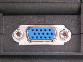
The Video Graphics Array (VGA) connector is a standard connector used for computer video output. Originating with the 1987 IBM PS/2 and its VGA graphics system, the 15-pin connector went on to become ubiquitous on PCs, as well as many monitors, projectors and high-definition television sets.
In electronics, a pinout is a cross-reference between the contacts, or pins, of an electrical connector or electronic component, and their functions. "Pinout" now supersedes the term "basing diagram" which was the standard terminology used by the manufacturers of vacuum tubes and the RMA. The RMA started its standardization in 1934, collecting and correlating tube data for registration at what was to become the EIA. The EIA now has many sectors reporting to it and sets what is known as EIA standards where all registered pinouts and registered jacks can be found.
RS-485, also known as TIA-485(-A) or EIA-485, is a standard, originally introduced in 1983, defining the electrical characteristics of drivers and receivers for use in serial communications systems. Electrical signaling is balanced, and multipoint systems are supported. The standard is jointly published by the Telecommunications Industry Association and Electronic Industries Alliance (TIA/EIA). Digital communications networks implementing the standard can be used effectively over long distances and in electrically noisy environments. Multiple receivers may be connected to such a network in a linear, multidrop bus. These characteristics make RS-485 useful in industrial control systems and similar applications.

Currently known as TIA-530-A, but often called EIA-530, or RS-530, is a balanced serial interface standard that generally uses a 25-pin connector, originally created by the Telecommunications Industry Association.
The Fibre Channel electrical interface is one of two related Fibre Channel standards that can be used to physically interconnect computer devices. The other standard is a Fibre Channel optical interface, which is not covered in this article.
A modular connector is a type of electrical connector for cords and cables of electronic devices and appliances, such as in computer networking, telecommunication equipment, and audio headsets.
Communications Specification for Fitness Equipment (CSAFE) is a fitness industry-wide communications specification developed in 1997 for exercise equipment. As this specification was originally developed by the company FitLinxx, sometimes it is also referred to as FitLinxx.
RS-423, also known as TIA/EIA-423, is a technical standard originated by the Electronic Industries Alliance that specifies electrical characteristics of a digital signaling circuit. Although it was originally intended as a successor to RS-232C offering greater cable lengths, it is not widely used.
Data Terminal Ready (DTR) is a control signal in RS-232 serial communications, transmitted from data terminal equipment (DTE), such as a computer, to data communications equipment (DCE), for example a modem, to indicate that the terminal is ready for communications and the modem may initiate a communications channel.
ANSI/TIA-568 is a technical standard for commercial building cabling for telecommunications products and services. The title of the standard is Commercial Building Telecommunications Cabling Standard and is published by the Telecommunications Industry Association (TIA), a body accredited by the American National Standards Institute (ANSI).
In telecommunications, RS-366, later known as EIA-366, defines a standard for serial communications between computers and an auto dialer, which is used to dial telephones. It was intended to be used to automate the operation of modems. The standard uses the same DB25 connectors and electrical signalling standards of the well-known RS-232 standard, which RS-366 was designed to support. The CCITT had a matching standard, V.25.
