Resistor ladder

Last updated

A resistor ladder is an electrical circuit made from repeating units of resistors, in specific configurations.

Contents

An R–2R ladder configuration is a simple and inexpensive way to perform digital-to-analog conversion (DAC), using repetitive arrangements of precise resistor networks in a ladder-like configuration.

History

A 1953 paper "Coding by Feedback Methods" [1] describes "decoding networks" that convert numbers (in any base) represented by voltage sources or current sources connected to resistor networks in a "shunt resistor decoding network" (which in base 2 corresponds to the binary-weighted configuration) or in a "ladder resistor decoding network" (which in base 2 corresponds to R–2R configuration) into a single voltage output. The paper gives an advantage of R–2R that impedances seen by the sources are more equal.

Another historic description is in US Patent 3108266, filed in 1955, "Signal Conversion Apparatus". [2]

Resistor string network

A string of many resistors connected between two reference voltages is called a "resistor string". The resistors act as voltage dividers between the referenced voltages. A Kelvin divider or string DAC is a string of equal valued resistors. [3]

Analog-to-digital conversion

Each tap of the string generates a different voltage, which can be compared with another voltage: this is the basic principle of a flash ADC (analog-to-digital converter). The main disadvantage is that this architecture requires comparators, one for each resistor; and this number cannot be reduced by using an R-2R network because such a network would not have separate outputs for each voltage.

Digital-to-analog conversion

A resistor string can function as a DAC by having the bits of the binary number control electronic switches connected to each tap. [4]

Binary weighted

The binary weighted configuration uses power of two multiples of a base resistor value. However, as the ratios of resistor values increases, the ability to trim the resistors to accurate ratio tolerances becomes diminished. More accurate ratios can be obtained by using similar values, as is used in R–2R ladder. Hence R–2R provides more accurate digital-to-analog conversion. [5] [6]

R–2R resistor ladder network (digital to analog conversion)

Figure 1: n-bit voltage mode R-2R resistor ladder DAC. R2r-ladder.png
Figure 1: n-bit voltage mode R–2R resistor ladder DAC.

Voltage Mode

A voltage mode R–2R resistor ladder network is shown in Figure 1. Bit an−1 (most significant bit, MSB) through bit a0 (least significant bit, LSB) are driven from digital logic gates. Ideally, the bit inputs are switched between V = 0 (logic 0) and V = Vref (logic 1). The R–2R network causes these digital bits to be weighted in their contribution to the output voltage Vout. Depending on which bits are set to 1 and which to 0, the output voltage (Vout) will have a corresponding stepped value between 0 and Vref minus the value of the minimal step, corresponding to bit 0. The actual value of Vref (and the voltage of logic 0) will depend on the type of technology used to generate the digital signals. [7]

For a digital value VAL, of a R–2R DAC with N bits and 0 V/Vref logic levels, the output voltage Vout is:

For example, if N = 5 (hence 2N = 32) and Vref = 3.3 V (typical CMOS logic 1 voltage), then Vout will vary between 0 volts (VAL = 0 = 000002) and the maximum (VAL = 31 = 111112):

with steps (corresponding to VAL = 1 = 000012)

The R–2R ladder is inexpensive and relatively easy to manufacture, since only two resistor values are required (or even one, if R is made by placing a pair of 2R in parallel, or if 2R is made by placing a pair of R in series). It is fast and has fixed output impedance R. The R–2R ladder operates as a string of current dividers, whose output accuracy is solely dependent on how well each resistor is matched to the others. Small inaccuracies in the MSB resistors can entirely overwhelm the contribution of the LSB resistors. This may result in non-monotonic behavior at major crossings, such as from 011112 to 100002.

Depending on the type of logic gates used and design of the logic circuits, there may be transitional voltage spikes at such major crossings even with perfect resistor values. These can be filtered with capacitance at the output node (the consequent reduction in bandwidth may be significant in some applications). Finally, the 2R resistance is in series with the digital-output impedance. High-output-impedance gates (e.g., LVDS) may be unsuitable in some cases. For all of the above reasons (and doubtless others), this type of DAC tends to be restricted to a relatively small number of bits; although integrated circuits may push the number of bits to 14 or even more, 8 bits or fewer is more typical.

The R–2R DAC described above directly outputs a voltage and so is called voltage mode (or sometimes normal mode).

Current Mode

Since the output impedance is independent of digital code, the analog output may equally-well be taken as a current into a virtual ground, a configuration called current mode (or sometimes inverted mode). Using current mode, the gain of the DAC may be adjusted with a series resistor at the reference voltage terminal. [8] The current for all bits pass through an equivalent resistance of 2R to ground. The less significant the bit, the more resistors its signal must pass through. At each node each bit's current is divided by two. [9]

Accuracy of R–2R resistor ladders

Resistors used with the more significant bits must be proportionally more accurate than those used with the less significant bits; for example, in the R–2R network discussed above, inaccuracies in the bit-4 (MSB) resistors must be insignificant compared to 132 (~3.1%) of R. Further, to avoid problems at the 100002-to-011112 transition, the sum of the inaccuracies in the lower bits must also be significantly less than that. The required accuracy doubles with each additional bit: for 8 bits, the accuracy required will be better than 1256 (~0.4%).[ clarification needed ]

However, variances for resistances when manufactured in a single component tend to be much lower than variances between components or between batches of manufacturing, and hence a resistor network can be purchased as a single component. And within integrated circuits, high-accuracy R–2R networks may be printed directly onto a single substrate using thin-film technology, ensuring the resistors share similar electrical characteristics. Even so, they must often be laser-trimmed to achieve the required precision. Such on-chip resistor ladders for digital-to-analog converters achieving 16-bit accuracy have been demonstrated. [10]

Resistor ladder with unequal rungs

Figure 2: 4-bit linear R-2R DAC using unequal resistors UnequalLadder.svg
Figure 2: 4-bit linear R–2R DAC using unequal resistors

It is not necessary that each "rung" of the R–2R ladder use the same resistor values. It is only necessary that the "2R" value matches the sum of the "R" value plus the Thévenin-equivalent resistance of the lower-significance rungs. Figure 2 shows a linear 4-bit DAC with unequal resistors.

This allows a reasonably accurate DAC to be created from a heterogeneous collection of resistors by forming the DAC one bit at a time. At each stage, resistors for the "rung" and "leg" are chosen so that the rung value matches the leg value plus the equivalent resistance of the previous rungs. The rung and leg resistors can be formed by pairing other resistors in series or parallel in order to increase the number of available combinations. This process can be automated.

See also

Related Research Articles

<span class="mw-page-title-main">Operational amplifier</span> High-gain voltage amplifier with a differential input

An operational amplifier is a DC-coupled electronic voltage amplifier with a differential input, a (usually) single-ended output, and an extremely high gain. Its name comes from its original use of performing mathematical operations in analog computers.

<span class="mw-page-title-main">Analog-to-digital converter</span> System that converts an analog signal into a digital signal

In electronics, an analog-to-digital converter is a system that converts an analog signal, such as a sound picked up by a microphone or light entering a digital camera, into a digital signal. An ADC may also provide an isolated measurement such as an electronic device that converts an analog input voltage or current to a digital number representing the magnitude of the voltage or current. Typically the digital output is a two's complement binary number that is proportional to the input, but there are other possibilities.

<span class="mw-page-title-main">Comparator</span> Device that compares two voltages or currents

In electronics, a comparator is a device that compares two voltages or currents and outputs a digital signal indicating which is larger. It has two analog input terminals and and one binary digital output . The output is ideally

<span class="mw-page-title-main">Digital-to-analog converter</span> Device that converts a digital signal into an analog signal

In electronics, a digital-to-analog converter is a system that converts a digital signal into an analog signal. An analog-to-digital converter (ADC) performs the reverse function.

<span class="mw-page-title-main">Inverter (logic gate)</span> Logic gate implementing negation

In digital logic, an inverter or NOT gate is a logic gate which implements logical negation. It outputs a bit opposite of the bit that is put into it. The bits are typically implemented as two differing voltage levels.

<span class="mw-page-title-main">Differential amplifier</span> Electrical circuit component which amplifies the difference of two analog signals

A differential amplifier is a type of electronic amplifier that amplifies the difference between two input voltages but suppresses any voltage common to the two inputs. It is an analog circuit with two inputs and and one output , in which the output is ideally proportional to the difference between the two voltages:

<span class="mw-page-title-main">Schmitt trigger</span> Electronic comparator circuit with hysteresis

In electronics, a Schmitt trigger is a comparator circuit with hysteresis implemented by applying positive feedback to the noninverting input of a comparator or differential amplifier. It is an active circuit which converts an analog input signal to a digital output signal. The circuit is named a trigger because the output retains its value until the input changes sufficiently to trigger a change. In the non-inverting configuration, when the input is higher than a chosen threshold, the output is high. When the input is below a different (lower) chosen threshold the output is low, and when the input is between the two levels the output retains its value. This dual threshold action is called hysteresis and implies that the Schmitt trigger possesses memory and can act as a bistable multivibrator. There is a close relation between the two kinds of circuits: a Schmitt trigger can be converted into a latch and a latch can be converted into a Schmitt trigger.

<span class="mw-page-title-main">Voltage divider</span> Linear circuit that produces an output voltage that is a fraction of its input voltage

In electronics, a voltage divider (also known as a potential divider) is a passive linear circuit that produces an output voltage (Vout) that is a fraction of its input voltage (Vin). Voltage division is the result of distributing the input voltage among the components of the divider. A simple example of a voltage divider is two resistors connected in series, with the input voltage applied across the resistor pair and the output voltage emerging from the connection between them.

RS-485, also known as TIA-485(-A) or EIA-485, is a standard, originally introduced in 1983, defining the electrical characteristics of drivers and receivers for use in serial communications systems. Electrical signaling is balanced, and multipoint systems are supported. The standard is jointly published by the Telecommunications Industry Association and Electronic Industries Alliance (TIA/EIA). Digital communications networks implementing the standard can be used effectively over long distances and in electrically noisy environments. Multiple receivers may be connected to such a network in a linear, multidrop bus. These characteristics make RS-485 useful in industrial control systems and similar applications.

<span class="mw-page-title-main">Covox Speech Thing</span> External digital-to-analog audio converter

The Covox Speech Thing is an external digital-to-analog converter (DAC) that plugs into the parallel printer port of a PC. It converts 8-bit digital sound using a simple R-2R resistor ladder into an analog signal output.

This article illustrates some typical operational amplifier applications. A non-ideal operational amplifier's equivalent circuit has a finite input impedance, a non-zero output impedance, and a finite gain. A real op-amp has a number of non-ideal features as shown in the diagram, but here a simplified schematic notation is used, many details such as device selection and power supply connections are not shown. Operational amplifiers are optimised for use with negative feedback, and this article discusses only negative-feedback applications. When positive feedback is required, a comparator is usually more appropriate. See Comparator applications for further information.

Open collector, open drain, open emitter, and open source refer to integrated circuit (IC) output pin configurations that process the IC's internal function through a transistor with an exposed terminal that is internally unconnected. One of the IC's internal high or low voltage rails typically connects to another terminal of that transistor. When the transistor is off, the output is internally disconnected from any internal power rail, a state called "high-impedance" (Hi-Z). Open outputs configurations thus differ from push–pull outputs, which use a pair of transistors to output a specific voltage or current.

A flash ADC is a type of analog-to-digital converter that uses a linear voltage ladder with a comparator at each "rung" of the ladder to compare the input voltage to successive reference voltages. Often these reference ladders are constructed of many resistors; however, modern implementations show that capacitive voltage division is also possible. The output of these comparators is generally fed into a digital encoder, which converts the inputs into a binary value.

A switched capacitor (SC) is an electronic circuit that implements a function by moving charges into and out of capacitors when electronic switches are opened and closed. Usually, non-overlapping clock signals are used to control the switches, so that not all switches are closed simultaneously. Filters implemented with these elements are termed switched-capacitor filters, which depend only on the ratios between capacitances and the switching frequency, and not on precise resistors. This makes them much more suitable for use within integrated circuits, where accurately specified resistors and capacitors are not economical to construct, but accurate clocks and accurate relative ratios of capacitances are economical.

<span class="mw-page-title-main">Successive-approximation ADC</span> Type of analog-to-digital converter

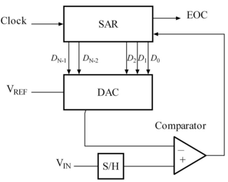
A successive-approximation ADC is a type of analog-to-digital converter (ADC) that converts a continuous analog waveform into a discrete digital representation using a binary search through all possible quantization levels before finally converging upon a digital output for each conversion.

<span class="mw-page-title-main">Digital potentiometer</span>

A digital potentiometer is a digitally-controlled electronic component that mimics the analog functions of a potentiometer. It is often used for trimming and scaling analog signals by microcontrollers.

<span class="mw-page-title-main">Differential nonlinearity</span>

Differential nonlinearity is a commonly used measure of performance in digital-to-analog (DAC) and analog-to-digital (ADC) converters. It is a term describing the deviation between two analog values corresponding to adjacent input digital values. It is an important specification for measuring error in a digital-to-analog converter (DAC); the accuracy of a DAC is mainly determined by this specification. Ideally, any two adjacent digital codes correspond to output analog voltages that are exactly one Least Significant Bit (LSB) apart. Differential non-linearity is a measure of the worst-case deviation from the ideal 1 LSB step. For example, a DAC with a 1.5 LSB output change for a 1 LSB digital code change exhibits 1⁄2 LSB differential non-linearity. Differential non-linearity may be expressed in fractional bits or as a percentage of full scale. A differential non-linearity greater than 1 LSB may lead to a non-monotonic transfer function in a DAC. It is also known as a missing code.

A log amplifier, also known as logarithmic amplifier or logarithm amplifier or log amp, is an amplifier for which the output voltage Vout is K times the natural log of the input voltage Vin. This can be expressed as,

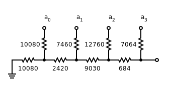
A logarithmic resistor ladder is an electronic circuit, composed of a series of resistors and switches, designed to create an attenuation from an input to an output signal, where the logarithm of the attenuation ratio is proportional to a binary number that represents the state of the switches.

The following outline is provided as an overview of and topical guide to electronics:

References

  1. Smith, B. D. (1953-08-01). "Coding by Feedback Methods" (PDF). Proceedings of the Institute of Radio Engineers. 41 (8): 1053–8. Archived (PDF) from the original on 2023-04-17 via worldradiohistory.com/Archive-IRE.
  2. U.S. Patent 3108266.: "Signal Conversion Apparatus", filed July 22, 1955.
  3. Kester, Walt (2009). "MT-014 Tutorial: Basic DAC Architectures I: String DACs and Thermometer (Fully Decoded) DACs" (PDF). Analog Devices . Archived (PDF) from the original on 2023-03-13. Retrieved 2023-07-06.
  4. https://inst.eecs.berkeley.edu/~ee247/fa08/files07/lectures/L14_2_f08.pdf
  5. Seams, Jerry. "R/2R Ladder Networks, AFD006" (Application Note). Retrieved 2023-11-28.
  6. TT Electronics. "R/2R Ladder Networks" (Application note).
  7. Logic Threshold Voltage Levels.
  8. Kester, Walt (2009). "MT-015 Tutorial: Basic DAC Architectures II: Binary DACs" (PDF). Analog Devices . Archived (PDF) from the original on 2022-10-06. Retrieved 2023-06-26.
  9. Fleming, Adam; Hunkele, Mark (2005-03-11). "Digital to Analog Converters (DAC)". Archived from the original (PPT) on 2022-04-02.
  10. http://www.ti.com/lit/ds/symlink/dac161s055.pdf [ bare URL PDF ]