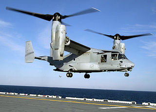
A tiltrotor is an aircraft that generates lift and propulsion by way of one or more powered rotors mounted on rotating shafts or nacelles usually at the ends of a fixed wing. Almost all tiltrotors use a transverse rotor design, with a few exceptions that use other multirotor layouts.

In fluid dynamics, a stall is a reduction in the lift coefficient generated by a foil as angle of attack increases. This occurs when the critical angle of attack of the foil is exceeded. The critical angle of attack is typically about 15°, but it may vary significantly depending on the fluid, foil, and Reynolds number.

The airspeed indicator (ASI) or airspeed gauge is a flight instrument indicating the airspeed of an aircraft in kilometres per hour (km/h), knots (kn), miles per hour (MPH) and/or metres per second (m/s). The recommendation by ICAO is to use km/h, however knots is currently the most used unit. The ASI measures the pressure differential between static pressure from the static port, and total pressure from the pitot tube. This difference in pressure is registered with the ASI pointer on the face of the instrument.
The CarterCopter is an experimental compound autogyro developed by Carter Aviation Technologies in the United States to demonstrate slowed rotor technology. On 17 June 2005, the CarterCopter became the first rotorcraft to achieve mu-1 (μ=1), an equal ratio of airspeed to rotor tip speed, but crashed on the next flight and has been inoperable since. It is being replaced by the Carter Personal Air Vehicle.

The vortex ring state (VRS) is a dangerous aerodynamic condition that may arise in helicopter flight, when a vortex ring system engulfs the rotor, causing severe loss of lift. Often the term settling with power is used as a synonym, e.g., in Australia, the UK, and the USA, but not in Canada, which uses the latter term for a different phenomenon.
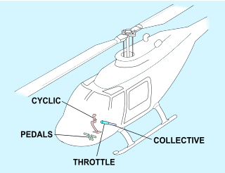
Helicopter flight controls are used to achieve and maintain controlled aerodynamic helicopter flight. Changes to the aircraft flight control system transmit mechanically to the rotor, producing aerodynamic effects on the rotor blades that make the helicopter move in a desired way. To tilt forward and back (pitch) or sideways (roll) requires that the controls alter the angle of attack of the main rotor blades cyclically during rotation, creating differing amounts of lift at different points in the cycle. To increase or decrease overall lift requires that the controls alter the angle of attack for all blades collectively by equal amounts at the same time, resulting in ascent, descent, acceleration and deceleration.

On a helicopter, the main rotor or rotor system is the combination of several rotary wings with a control system, that generates the aerodynamic lift force that supports the weight of the helicopter, and the thrust that counteracts aerodynamic drag in forward flight. Each main rotor is mounted on a vertical mast over the top of the helicopter, as opposed to a helicopter tail rotor, which connects through a combination of drive shaft(s) and gearboxes along the tail boom. The blade pitch is typically controlled by the pilot using the helicopter flight controls. Helicopters are one example of rotary-wing aircraft (rotorcraft). The name is derived from the Greek words helix, helik-, meaning spiral; and pteron meaning wing.

A rotorcraft or rotary-wing aircraft is a heavier-than-air aircraft with rotary wings or rotor blades, which generate lift by rotating around a vertical mast. Several rotor blades mounted on a single mast are referred to as a rotor. The International Civil Aviation Organization (ICAO) defines a rotorcraft as "supported in flight by the reactions of the air on one or more rotors".

P-factor, also known as asymmetric blade effect and asymmetric disc effect, is an aerodynamic phenomenon experienced by a moving propeller, wherein the propeller's center of thrust moves off-center when the aircraft is at a high angle of attack. This shift in the location of the center of thrust will exert a yawing moment on the aircraft, causing it to yaw slightly to one side. A rudder input is required to counteract the yawing tendency.
In the aerodynamics of rotorcraft like helicopters, phase lag refers to the angular difference between the point at which a control input to a rotor blade occurs and the point of maximum displacement of the blade in response to that control input. This displacement occurs in the direction of rotor rotation. Phase lag may vary depending on rotor tilt rate, ratio of aerodynamic damping to blade inertial forces, offset of flapping hinge from axis of rotation, and coupling of blade flap, drag, and feather motions, and often results in cross-coupling between the aircraft control axes. Phase lag is a property of all rotating systems acted upon by a periodic force.
Transverse flow effect is an aerodynamic effect encountered when a helicopter moves horizontally through the air, which causes the rotor disc to roll to the side. It is also known as transverse roll or inflow roll.

In aeronautics, an aircraft propeller, also called an airscrew, converts rotary motion from an engine or other power source into a swirling slipstream which pushes the propeller forwards or backwards. It comprises a rotating power-driven hub, to which are attached several radial airfoil-section blades such that the whole assembly rotates about a longitudinal axis. The blade pitch may be fixed, manually variable to a few set positions, or of the automatically variable "constant-speed" type.

Dissymmetry of lift in rotorcraft aerodynamics refers to an unequal amount of lift on opposite sides of the rotor disc. It is a phenomenon that affects single-rotor helicopters and autogyros in forward flight.

A helicopter is a type of rotorcraft in which lift and thrust are supplied by horizontally spinning rotors. This allows the helicopter to take off and land vertically, to hover, and to fly forward, backward and laterally. These attributes allow helicopters to be used in congested or isolated areas where fixed-wing aircraft and many forms of short take-off and landing (STOL) or short take-off and vertical landing (STOVL) aircraft cannot perform without a runway.
Flapback or blowback is the tilting of a helicopter rotor disc, usually aft (backwards), which occurs in several circumstances.
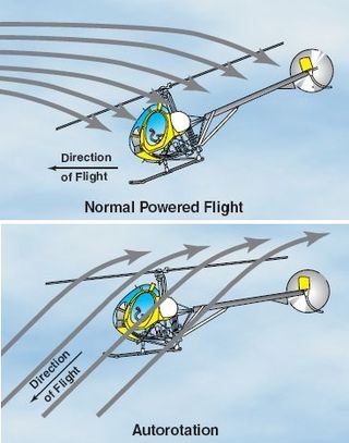
Autorotation is a state of flight in which the main rotor system of a helicopter or other rotary-wing aircraft turns by the action of air moving up through the rotor, as with an autogyro, rather than engine power driving the rotor. The term autorotation dates to a period of early helicopter development between 1915 and 1920, and refers to the rotors turning without the engine. It is analogous to the gliding flight of a fixed-wing aircraft. Some trees have seeds that have evolved wing-like structures that enable the seed to spin to the ground in autorotation, which helps the seeds to disseminate over a wider area.
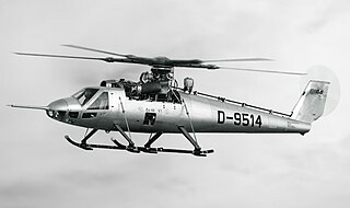
The Bölkow Bo 46 was a West German experimental helicopter built to test the Derschmidt rotor system that aimed to allow much higher speeds than traditional helicopter designs. Wind tunnel testing showed promise, but the Bo 46 demonstrated a number of problems and added complexity that led to the concept being abandoned. The Bo 46 was one of a number of new designs exploring high-speed helicopter flight that were built in the early 1960s.

The slowed rotor principle is used in the design of some helicopters. On a conventional helicopter the rotational speed of the rotor is constant; reducing it at lower flight speeds can reduce fuel consumption and enable the aircraft to fly more economically. In the compound helicopter and related aircraft configurations such as the gyrodyne and winged autogyro, reducing the rotational speed of the rotor and offloading part of its lift to a fixed wing reduces drag, enabling the aircraft to fly faster.
A rotor wing is a lifting rotor or wing which spins to provide aerodynamic lift. In general, a rotor may spin about an axis which is aligned substantially either vertically or side-to-side (spanwise). All three classes have been studied for use as lifting rotors and several variations have been flown on full-size aircraft, although only the vertical-axis rotary wing has become widespread on rotorcraft such as the helicopter.

The dynamic stall is one of the hazardous phenomena on helicopter rotors, which can cause the onset of large torsional airloads and vibrations on the rotor blades. Unlike fixed-wing aircraft, of which the stall occurs at relatively low flight speed, the dynamic stall on a helicopter rotor emerges at high airspeeds or/and during manoeuvres with high load factors of helicopters, when the angle of attack(AOA) of blade elements varies intensively due to time-dependent blade flapping, cyclic pitch and wake inflow. For example, during forward flight at the velocity close to VNE, velocity, never exceed, the advancing and retreating blades almost reach their operation limits whereas flows are still attached to the blade surfaces. That is, the advancing blades operate at high Mach numbers so low values of AOA is needed but shock-induced flow separation may happen, while the retreating blade operates at much lower Mach numbers but the high values of AoA result in the stall.