
In mechanics, acceleration is the rate of change of the velocity of an object with respect to time. Acceleration is one of several components of kinematics, the study of motion. Accelerations are vector quantities. The orientation of an object's acceleration is given by the orientation of the net force acting on that object. The magnitude of an object's acceleration, as described by Newton's Second Law, is the combined effect of two causes:
In physics, the Coriolis force is an inertial force that acts on objects in motion within a frame of reference that rotates with respect to an inertial frame. In a reference frame with clockwise rotation, the force acts to the left of the motion of the object. In one with anticlockwise rotation, the force acts to the right. Deflection of an object due to the Coriolis force is called the Coriolis effect. Though recognized previously by others, the mathematical expression for the Coriolis force appeared in an 1835 paper by French scientist Gaspard-Gustave de Coriolis, in connection with the theory of water wheels. Early in the 20th century, the term Coriolis force began to be used in connection with meteorology.
Precession is a change in the orientation of the rotational axis of a rotating body. In an appropriate reference frame it can be defined as a change in the first Euler angle, whereas the third Euler angle defines the rotation itself. In other words, if the axis of rotation of a body is itself rotating about a second axis, that body is said to be precessing about the second axis. A motion in which the second Euler angle changes is called nutation. In physics, there are two types of precession: torque-free and torque-induced.

A pendulum is a device made of a weight suspended from a pivot so that it can swing freely. When a pendulum is displaced sideways from its resting, equilibrium position, it is subject to a restoring force due to gravity that will accelerate it back toward the equilibrium position. When released, the restoring force acting on the pendulum's mass causes it to oscillate about the equilibrium position, swinging back and forth. The time for one complete cycle, a left swing and a right swing, is called the period. The period depends on the length of the pendulum and also to a slight degree on the amplitude, the width of the pendulum's swing.

A gyroscope is a device used for measuring or maintaining orientation and angular velocity. It is a spinning wheel or disc in which the axis of rotation is free to assume any orientation by itself. When rotating, the orientation of this axis is unaffected by tilting or rotation of the mounting, according to the conservation of angular momentum.

A gyrocompass is a type of non-magnetic compass which is based on a fast-spinning disc and the rotation of the Earth to find geographical direction automatically. A gyrocompass makes use of one of the seven fundamental ways to determine the heading of a vehicle. A gyroscope is an essential component of a gyrocompass, but they are different devices; a gyrocompass is built to use the effect of gyroscopic precession, which is a distinctive aspect of the general gyroscopic effect. Gyrocompasses, such as the fibre optic gyrocompass are widely used to provide a heading for navigation on ships. This is because they have two significant advantages over magnetic compasses:
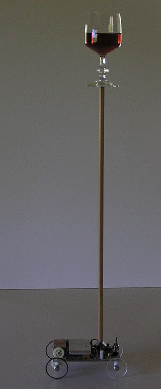
An inverted pendulum is a pendulum that has its center of mass above its pivot point. It is unstable and without additional help will fall over. It can be suspended stably in this inverted position by using a control system to monitor the angle of the pole and move the pivot point horizontally back under the center of mass when it starts to fall over, keeping it balanced. The inverted pendulum is a classic problem in dynamics and control theory and is used as a benchmark for testing control strategies. It is often implemented with the pivot point mounted on a cart that can move horizontally under control of an electronic servo system as shown in the photo; this is called a cart and pole apparatus. Most applications limit the pendulum to 1 degree of freedom by affixing the pole to an axis of rotation. Whereas a normal pendulum is stable when hanging downwards, an inverted pendulum is inherently unstable, and must be actively balanced in order to remain upright; this can be done either by applying a torque at the pivot point, by moving the pivot point horizontally as part of a feedback system, changing the rate of rotation of a mass mounted on the pendulum on an axis parallel to the pivot axis and thereby generating a net torque on the pendulum, or by oscillating the pivot point vertically. A simple demonstration of moving the pivot point in a feedback system is achieved by balancing an upturned broomstick on the end of one's finger.

The attitude indicator (AI), formerly known as the gyro horizon or artificial horizon, is a flight instrument that informs the pilot of the aircraft orientation relative to Earth's horizon, and gives an immediate indication of the smallest orientation change. The miniature aircraft and horizon bar mimic the relationship of the aircraft relative to the actual horizon. It is a primary instrument for flight in instrument meteorological conditions.

An accelerometer is a device that measures the proper acceleration of an object. Proper acceleration is the acceleration of the object relative to an observer who is in free fall. Proper acceleration is different from coordinate acceleration, which is acceleration with respect to a given coordinate system, which may or may not be accelerating. For example, an accelerometer at rest on the surface of the Earth will measure an acceleration due to Earth's gravity straight upwards of about g ≈ 9.81 m/s2. By contrast, an accelerometer that is in free fall will measure zero acceleration.
A gimbal is a pivoted support that permits rotation of an object about an axis. A set of three gimbals, one mounted on the other with orthogonal pivot axes, may be used to allow an object mounted on the innermost gimbal to remain independent of the rotation of its support. For example, on a ship, the gyroscopes, shipboard compasses, stoves, and even drink holders typically use gimbals to keep them upright with respect to the horizon despite the ship's pitching and rolling.

Gravimetry is the measurement of the strength of a gravitational field. Gravimetry may be used when either the magnitude of a gravitational field or the properties of matter responsible for its creation are of interest. The study of gravity changes belongs to geodynamics.

Clairaut's theorem characterizes the surface gravity on a viscous rotating ellipsoid in hydrostatic equilibrium under the action of its gravitational field and centrifugal force. It was published in 1743 by Alexis Claude Clairaut in a treatise which synthesized physical and geodetic evidence that the Earth is an oblate rotational ellipsoid. It was initially used to relate the gravity at any point on the Earth's surface to the position of that point, allowing the ellipticity of the Earth to be calculated from measurements of gravity at different latitudes. Today it has been largely supplanted by the Somigliana equation.

A gravity train is a theoretical means of transportation for purposes of commuting between two points on the surface of a sphere, by following a straight tunnel connecting the two points through the interior of the sphere.
The Eötvös effect is the change in measured Earth's gravity caused by the change in centrifugal acceleration resulting from eastbound or westbound velocity. When moving eastbound, the object's angular velocity is increased, and thus the centrifugal force also increases, causing a perceived reduction in gravitational force.

Bicycle and motorcycle dynamics is the science of the motion of bicycles and motorcycles and their components, due to the forces acting on them. Dynamics falls under a branch of physics known as classical mechanics. Bike motions of interest include balancing, steering, braking, accelerating, suspension activation, and vibration. The study of these motions began in the late 19th century and continues today.
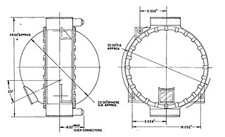
The ST-124-M3 inertial platform was a device for measuring acceleration and attitude of the Saturn V launch vehicle. It was carried by the Saturn V Instrument Unit, a 3-foot-high (0.91 m), 22-foot-diameter (6.7 m) section of the Saturn V that fit between the third stage (S-IVB) and the Apollo spacecraft. Its nomenclature means "stable table" (ST) for use in the Moon mission (M), and it has 3 gimbals.
A PIGA is a type of accelerometer that can measure acceleration and simultaneously integrates this acceleration against time to produce a speed measure as well. The PIGA's main use is in Inertial Navigation Systems (INS) for guidance of aircraft and most particularly for ballistic missile guidance. It is valued for its extremely high sensitivity and accuracy in conjunction with operation over a wide acceleration range. The PIGA is still considered the premier instrument for strategic grade missile guidance, though systems based on MEMS technology are attractive for lower performance requirements.

An inertial navigation system is a navigation device that uses motion sensors (accelerometers), rotation sensors (gyroscopes) and a computer to continuously calculate by dead reckoning the position, the orientation, and the velocity of a moving object without the need for external references. Often the inertial sensors are supplemented by a barometric altimeter and sometimes by magnetic sensors (magnetometers) and/or speed measuring devices. INSs are used on mobile robots and on vehicles such as ships, aircraft, submarines, guided missiles, and spacecraft. Older INS systems generally used an inertial platform as their mounting point to the vehicle and the terms are sometimes considered synonymous.

The LN-3 inertial navigation system is an inertial navigation system (INS) that was developed in the 1960s by Litton Industries. It equipped the Lockheed F-104 Starfighter versions used as strike aircraft in European forces. An inertial navigation system is a system which continually determines the position of a vehicle from measurements made entirely within the vehicle using sensitive instruments. These instruments are accelerometers which detect and measure vehicle accelerations, and gyroscopes which act to hold the accelerometers in proper orientation.
Spacecraft attitude control is the process of controlling the orientation of a spacecraft with respect to an inertial frame of reference or another entity such as the celestial sphere, certain fields, and nearby objects, etc.


