
An ammeter is an instrument used to measure the current in a circuit. Electric currents are measured in amperes (A), hence the name. For direct measurement, the ammeter is connected in series with the circuit in which the current is to be measured. An ammeter usually has low resistance so that it does not cause a significant voltage drop in the circuit being measured.

A relay is an electrically operated switch. It consists of a set of input terminals for a single or multiple control signals, and a set of operating contact terminals. The switch may have any number of contacts in multiple contact forms, such as make contacts, break contacts, or combinations thereof.
A voltmeter is an instrument used for measuring electric potential difference between two points in an electric circuit. It is connected in parallel. It usually has a high resistance so that it takes negligible current from the circuit.

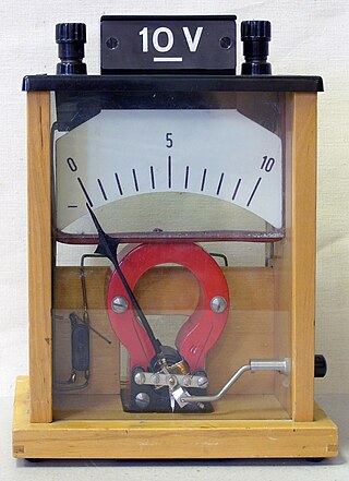
A galvanometer is an electromechanical measuring instrument for electric current. Early galvanometers were uncalibrated, but improved versions, called ammeters, were calibrated and could measure the flow of current more precisely.
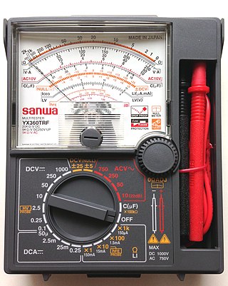
A multimeter is a measuring instrument that can measure multiple electrical properties. A typical multimeter can measure voltage, resistance, and current, in which case can be used as a voltmeter, ammeter, and ohmmeter. Some feature the measurement of additional properties such as temperature and capacitance.

Electronic test equipment is used to create signals and capture responses from electronic devices under test (DUTs). In this way, the proper operation of the DUT can be proven or faults in the device can be traced. Use of electronic test equipment is essential to any serious work on electronics systems.
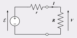
In electrical engineering, a practical electric power source which is a linear circuit may, according to Thévenin's theorem, be represented as an ideal voltage source in series with an impedance. This impedance is termed the internal resistance of the source. When the power source delivers current, the measured voltage output is lower than the no-load voltage; the difference is the voltage drop caused by the internal resistance. The concept of internal resistance applies to all kinds of electrical sources and is useful for analyzing many types of circuits.
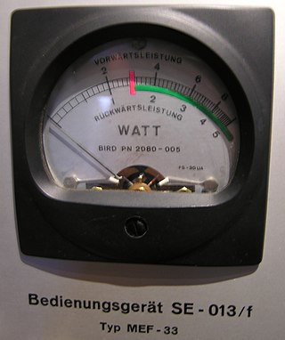
The wattmeter is an instrument for measuring the electric active power in watts of any given circuit. Electromagnetic wattmeters are used for measurement of utility frequency and audio frequency power; other types are required for radio frequency measurements.

A test light, test lamp, voltage tester, or mains tester is a piece of electronic test equipment used to determine the presence of electricity in a piece of equipment under test. A test light is simpler and less costly than a measuring instrument such as a multimeter, and often suffices for checking for the presence of voltage on a conductor. Properly designed test lights include features to protect the user from accidental electric shock. Non-contact test lights can detect voltage on insulated conductors.

A continuity tester is an item of electrical test equipment used to determine if an electrical path can be established between two points; that is if an electrical circuit can be made. The circuit under test is completely de-energized prior to connecting the apparatus.

A test probe is a physical device used to connect electronic test equipment to a device under test (DUT). Test probes range from very simple, robust devices to complex probes that are sophisticated, expensive, and fragile. Specific types include test prods, oscilloscope probes and current probes. A test probe is often supplied as a test lead, which includes the probe, cable and terminating connector.
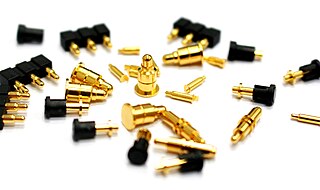
A pogo pin or spring-loaded pin is a type of electrical connector mechanism that is used in many modern electronic applications and in the electronics testing industry. They are used for their improved durability over other electrical contacts, and the resilience of their electrical connection to mechanical shock and vibration.

Stray voltage is the occurrence of electrical potential between two objects that ideally should not have any voltage difference between them. Small voltages often exist between two grounded objects in separate locations, due to normal current flow in the power system. Contact voltage is a better defined term when large voltage appear as a result of a fault. Contact voltage on the enclosure of electrical equipment can appear due to a fault in the electrical power system, such as a failure of insulation.

An electrical outlet tester, receptacle tester, or socket tester is a small device containing a 3-prong power plug and three indicator lights, used for quickly detecting some types of incorrectly-wired electrical wall outlets or campsite supplies.

Electrostatic voltmeter can refer to an electrostatic charge meter, known also as surface DC voltmeter, or to a voltmeter to measure large electrical potentials, traditionally called electrostatic voltmeter.

A Megohmmeter or insulation resistance tester, also colloquially known as megger, is a special type of ohmmeter used to measure the electrical resistance of insulators. Insulating components, for example cable jackets, must be tested for their insulation strength at the time of commissioning and as part of maintenance of high voltage electrical equipment and installations.

A tube tester is an electronic instrument designed to test certain characteristics of vacuum tubes. Tube testers evolved along with the vacuum tube to satisfy the demands of the time, and their evolution ended with the tube era. The first tube testers were simple units designed for specific tubes to be used in the battlefields of World War I by radio operators, so they could easily test the tubes of their communication equipment.
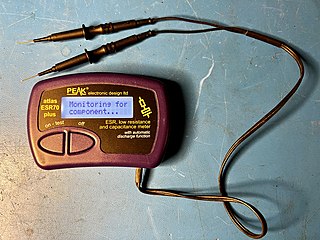
An ESR meter is a two-terminal electronic measuring instrument designed and used primarily to measure the equivalent series resistance (ESR) of real capacitors; usually without the need to disconnect the capacitor from the circuit it is connected to. Other types of meters used for routine servicing, including normal capacitance meters, cannot be used to measure a capacitor's ESR, although combined meters are available that measure both ESR and out-of-circuit capacitance. A standard (DC) milliohmmeter or multimeter cannot be used to measure ESR, because a steady direct current cannot be passed through the capacitor. Most ESR meters can also be used to measure non-inductive low-value resistances, whether or not associated with a capacitor; this leads to several additional applications described below.

The purpose of a short-circuit test is to determine the series branch parameters of the equivalent circuit of a transformer.
In engineering, a solenoid is a device that converts electrical energy to mechanical energy, using an electromagnet formed from a coil of wire. The device creates a magnetic field from electric current, and uses the magnetic field to create linear motion. In electromagnetic technology, a solenoid is an actuator assembly with a sliding ferromagnetic plunger inside the coil. Without power, the plunger extends for part of its length outside the coil; applying power pulls the plunger into the coil. Electromagnets with fixed cores are not considered solenoids. In simple terms, a solenoid converts electrical energy into mechanical work. Typically, it has a multiturn coil of magnet wire surrounded by a frame, which is also a magnetic flux carrier to enhance its efficiency. In engineering, the term may also refer to a variety of transducer devices that convert energy into linear motion, more sophisticated than simple two–position actuators. The term "solenoid" also often refers to a solenoid valve, an integrated device containing an electromechanical solenoid which actuates either a pneumatic or hydraulic valve, or a solenoid switch, which is a specific type of relay that internally uses an electromechanical solenoid to operate an electrical switch; for example, an automobile starter solenoid or linear solenoid. Solenoid bolts, a type of electromechanical locking mechanism, also exist.
