
An electrical network is an interconnection of electrical components or a model of such an interconnection, consisting of electrical elements. An electrical circuit is a network consisting of a closed loop, giving a return path for the current. Thus all circuits are networks, but not all networks are circuits. Linear electrical networks, a special type consisting only of sources, linear lumped elements, and linear distributed elements, have the property that signals are linearly superimposable. They are thus more easily analyzed, using powerful frequency domain methods such as Laplace transforms, to determine DC response, AC response, and transient response.

An amplifier, electronic amplifier or (informally) amp is an electronic device that can increase the magnitude of a signal. It is a two-port electronic circuit that uses electric power from a power supply to increase the amplitude of a signal applied to its input terminals, producing a proportionally greater amplitude signal at its output. The amount of amplification provided by an amplifier is measured by its gain: the ratio of output voltage, current, or power to input. An amplifier is defined as a circuit that has a power gain greater than one.

An operational amplifier is a DC-coupled high-gain electronic voltage amplifier with a differential input and, usually, a single-ended output. In this configuration, an op amp produces an output potential that is typically 100,000 times larger than the potential difference between its input terminals. The operational amplifier traces its origin and name to analog computers, where they were used to perform mathematical operations in linear, non-linear, and frequency-dependent circuits.

In electrical engineering, impedance is the opposition to alternating current presented by the combined effect of resistance and reactance in a circuit.
In electrical engineering, electrical elements are conceptual abstractions representing idealized electrical components, such as resistors, capacitors, and inductors, used in the analysis of electrical networks. All electrical networks can be analyzed as multiple electrical elements interconnected by wires. Where the elements roughly correspond to real components, the representation can be in the form of a schematic diagram or circuit diagram. This is called a lumped-element circuit model. In other cases, infinitesimal elements are used to model the network in a distributed-element model.

A negative-feedback amplifier is an electronic amplifier that subtracts a fraction of its output from its input, so that negative feedback opposes the original signal. The applied negative feedback can improve its performance and reduces sensitivity to parameter variations due to manufacturing or environment. Because of these advantages, many amplifiers and control systems use negative feedback.

Johnson–Nyquist noise is the electronic noise generated by the thermal agitation of the charge carriers inside an electrical conductor at equilibrium, which happens regardless of any applied voltage. Thermal noise is present in all electrical circuits, and in sensitive electronic equipment can drown out weak signals, and can be the limiting factor on sensitivity of electrical measuring instruments. Thermal noise increases with temperature. Some sensitive electronic equipment such as radio telescope receivers are cooled to cryogenic temperatures to reduce thermal noise in their circuits. The generic, statistical physical derivation of this noise is called the fluctuation-dissipation theorem, where generalized impedance or generalized susceptibility is used to characterize the medium.

In direct-current circuit theory, Norton's theorem, also called the Mayer–Norton theorem, is a simplification that can be applied to networks made of linear time-invariant resistances, voltage sources, and current sources. At a pair of terminals of the network, it can be replaced by a current source and a single resistor in parallel.

As originally stated in terms of direct-current resistive circuits only, Thévenin's theorem states that "Any linear electrical network containing only voltage sources, current sources and resistances can be replaced at terminals A–B by an equivalent combination of a voltage source Vth in a series connection with a resistance Rth."

The output impedance of an electrical network is the measure of the opposition to current flow (impedance), both static (resistance) and dynamic (reactance), into the load network being connected that is internal to the electrical source. The output impedance is a measure of the source's propensity to drop in voltage when the load draws current, the source network being the portion of the network that transmits and the load network being the portion of the network that consumes.
In electrical engineering and electronics, a network is a collection of interconnected components. Network analysis is the process of finding the voltages across, and the currents through, all network components. There are many techniques for calculating these values; however, for the most part, the techniques assume linear components. Except where stated, the methods described in this article are applicable only to linear network analysis.

A current source is an electronic circuit that delivers or absorbs an electric current which is independent of the voltage across it.
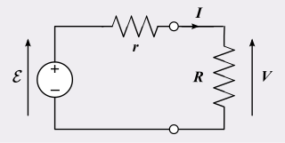
In electrical engineering, a practical electric power source which is a linear circuit may, according to Thévenin's theorem, be represented as an ideal voltage source in series with an impedance. This impedance is termed the internal resistance of the source. When the power source delivers current, the measured voltage output is lower than the no-load voltage; the difference is the voltage drop caused by the internal resistance. The concept of internal resistance applies to all kinds of electrical sources and is useful for analyzing many types of circuits.
In electrical engineering, an equivalent circuit refers to a theoretical circuit that retains all of the electrical characteristics of a given circuit. Often, an equivalent circuit is sought that simplifies calculation, and more broadly, that is a simplest form of a more complex circuit in order to aid analysis. In its most common form, an equivalent circuit is made up of linear, passive elements. However, more complex equivalent circuits are used that approximate the nonlinear behavior of the original circuit as well. These more complex circuits often are called macromodels of the original circuit. An example of a macromodel is the Boyle circuit for the 741 operational amplifier.

The superposition principle, also known as superposition property, states that, for all linear systems, the net response caused by two or more stimuli is the sum of the responses that would have been caused by each stimulus individually. So that if input A produces response X and input B produces response Y then input (A + B) produces response (X + Y).

A voltage source is a two-terminal device which can maintain a fixed voltage. An ideal voltage source can maintain the fixed voltage independent of the load resistance or the output current. However, a real-world voltage source cannot supply unlimited current.
Small-signal modeling is a common analysis technique in electronics engineering used to approximate the behavior of electronic circuits containing nonlinear devices with linear equations. It is applicable to electronic circuits in which the AC signals are small relative to the DC bias currents and voltages. A small-signal model is an AC equivalent circuit in which the nonlinear circuit elements are replaced by linear elements whose values are given by the first-order (linear) approximation of their characteristic curve near the bias point.
Mathematical methods are integral to the study of electronics.
Bartlett's bisection theorem is an electrical theorem in network analysis attributed to Albert Charles Bartlett. The theorem shows that any symmetrical two-port network can be transformed into a lattice network. The theorem often appears in filter theory where the lattice network is sometimes known as a filter X-section following the common filter theory practice of naming sections after alphabetic letters to which they bear a resemblance.
The Miller theorem refers to the process of creating equivalent circuits. It asserts that a floating impedance element, supplied by two voltage sources connected in series, may be split into two grounded elements with corresponding impedances. There is also a dual Miller theorem with regards to impedance supplied by two current sources connected in parallel. The two versions are based on the two Kirchhoff's circuit laws.