The first version, the Transmission System 1 (T1), was introduced in 1962 in the Bell System, and could transmit up to 24 telephone calls simultaneously over a single transmission line of copper wire. Subsequent specifications carried multiples of the basic T1 (1.544Mbit/s) data rates, such as T2 (6.312Mbit/s) with 96 channels, T3 (44.736Mbit/s) with 672 channels, and others.
Although a T2 was defined as part of AT&T's T-carrier system, which defined five levels, T1 through T5,[1] only the T1 and T3 were commonly in use.[2][1]
The T-carriers are commonly used for trunking between switching centers in a telephone network, including to private branch exchange (PBX) interconnect points. It uses the same twisted paircopper wire that analog trunks used, employing one pair for transmitting, and another pair for receiving. Signal repeaters may be used for extended distance requirements.
Outside of the United States, Canada, Japan, and South Korea, the E-carrier system is used. E-carrier is similar transmission system with higher capacity that is not directly compatible with the T-carrier.
Legacy
Existing frequency-division multiplexing carrier systems worked well for connections between distant cities, but required expensive modulators, demodulators and filters for every voice channel. In the late 1950s, Bell Labs sought cheaper terminal equipment for connections within metropolitan areas. Pulse-code modulation allowed sharing a coder and decoder among several voice trunks, so this method was chosen for the T1 system introduced into local use in 1961. In later decades, the cost of digital electronics declined to the point that an individual codec per voice channel became commonplace, but by then the other advantages of digital transmission had become entrenched.
The T1 format carried 24 pulse-code modulated, time-division multiplexed speech signals each encoded in 64kbit/s streams, leaving 8kbit/s of framing information which facilitates the synchronization and demultiplexing at the receiver. The T2 and T3 circuit channels carry multiple T1 channels multiplexed, resulting in transmission rates of 6.312 and 44.736Mbit/s, respectively. A T3 line comprises 28 T1 lines, each operating at total signaling rate of 1.544Mbit/s. It is possible to get a fractional T3 line,[4][5] meaning a T3 line with some of the 28 lines turned off, resulting in a slower transfer rate but typically at reduced cost.
Supposedly, the 1.544 Mbit/s rate was chosen because tests by AT&T Long Lines in Chicago were conducted underground.[citation needed] The test site was typical of Bell System outside plant of the time in that, to accommodate loading coils, cable vault manholes were physically 2,000 meters (6,600 feet) apart, which determined the repeater spacing. The optimum bit rate was chosen empirically—the capacity was increased until the failure rate was unacceptable, then reduced to leave a margin. Companding allowed acceptable audio performance with only seven bits per PCM sample in this original T1/D1 system. The later D3 and D4 channel banks had an extended frame format, allowing eight bits per sample, reduced to seven every sixth sample or frame when one bit was "robbed" for signaling the state of the channel. The standard does not allow an all zero sample which would produce a long string of binary zeros and cause the repeaters to lose bit sync. However, when carrying data (Switched 56) there could be long strings of zeros, so one bit per sample is set to "1" (jam bit 7) leaving 7 bits × 8,000 frames per second for data.
A more detailed understanding of the development of the 1.544Mbit/s rate and its division into channels is as follows. Given that the telephone system nominal voiceband (including guardband) is 4,000Hz, the required digital sampling rate is 8,000Hz (see Nyquist rate). Since each T1 frame contains 1 byte of voice data for each of the 24 channels, that system needs then 8,000 frames per second to maintain those 24 simultaneous voice channels. Because each frame of a T1 is 193 bits in length (24 channels × 8 bits per channel + 1 framing bit = 193 bits), 8,000 frames per second is multiplied by 193 bits to yield a transfer rate of 1.544Mbit/s (8,000 × 193 = 1,544,000).
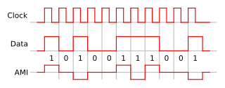
Initially, T1 used Alternate Mark Inversion (AMI) to reduce frequency bandwidth and eliminate the DC component of the signal. Later B8ZS became common practice. For AMI, each mark pulse had the opposite polarity of the previous one and each space was at a level of zero, resulting in a three level signal which carried only binary data. Similar 1970s British 23 channel systems at 1.536 megabaud were equipped with ternary signal repeaters, in anticipation of using a 3B2T or 4B3T code to increase the number of voice channels in the future. But in the 1980s, the systems were merely replaced with European standard ones. American T-carriers could only work in AMI or B8ZS mode.
The AMI or B8ZS signal allowed a simple error rate measurement. The D bank in the central office could detect a bit with the wrong polarity, or "bipolarity violation" and sound an alarm. Later systems could count the number of violations and reframes and otherwise measure signal quality and allow a more sophisticated alarm indication signal system.
The decision to use a 193-bit frame was made in 1958. To allow for the identification of information bits within a frame, two alternatives were considered. Assign (a) just one extra bit, or (b) additional eight bits per frame. The 8-bit choice is cleaner, resulting in a 200-bit frame, twenty-five 8-bit channels, of which 24 are traffic and one 8-bit channel available for operations, administration, and maintenance (OA&M). AT&T chose the single bit per frame not to reduce the required bit rate (1.544 vs 1.6Mbit/s), but because AT&T Marketing worried that "if 8 bits were chosen for OA&M function, someone would then try to sell this as a voice channel and you wind up with nothing."[citation needed]
Soon after commercial success of T1 in 1962, the T1 engineering team realized the mistake of having only one bit to serve the increasing demand for housekeeping functions. They petitioned AT&T management to change to 8-bit framing. This was flatly turned down because it would make installed systems obsolete.
Having this hindsight, some ten years later, CEPT chose eight bits for framing the European E1, although, as feared, the extra channel is sometimes appropriated for voice or data.
Higher bandwidth carriers
In the 1970s, Bell Labs developed higher rate systems. T1C with a more sophisticated modulation scheme carried 3Mbit/s, on those balanced pair cables that could support it. T-2 carried 6.312Mbit/s, requiring a special low-capacitance cable with foam insulation. This was standard for Picturephone. T-4 and T-5 used coaxial cables, similar to the old L-carriers used by AT&T Long Lines. TD microwave radio relay systems were also fitted with high rate modems to allow them to carry a DS1 signal in a portion of their FM spectrum that had too poor quality for voice service.[6] Later they carried DS3 and DS4 signals. During the 1980s companies such as RLH Industries, Inc. developed T1 over optical fiber. The industry soon developed and evolved with multiplexed T1 transmission schemes.
Digital signal cross-connect
DS1 signals are interconnected typically at Central Office locations at a common metallic cross-connect point known as a DSX-1. When a DS1 is transported over metallic outside plant cable, the signal travels over conditioned cable pairs known as a T1 span. A T1 span can have up to +-130 Volts of DC power superimposed on the associated four wire cable pairs to supply power to line or "Span" signal repeaters, and T1 NIU's (T1 Smartjacks). T1 span repeaters are typically engineered up to 6,000 feet (1,800m) apart, depending on cable gauge, and at no more than 36dB of loss before requiring a repeated span. There can be no cable bridge taps or Load Coils across any pairs.
T1 copper spans are being replaced by optical transport systems, but if a copper (Metallic) span is used, the T1 is typically carried over an HDSL encoded copper line. Four wire HDSL does not require as many repeaters as conventional T1 spans. Newer two wire HDSL (HDSL-2) equipment transports a full 1.544Mbit/s T1 over a single copper wire pair up to approximately twelve thousand (12,000) feet (3.5km), if all 24 gauge cable is used. HDSL-2 does not employ multiple repeaters as does conventional four wire HDSL, or newer HDSL-4 systems.
One advantage of HDSL is its ability to operate with a limited number of bridge taps, with no tap being closer than 500 feet (150m) from any HDSL transceiver. Both two or four wire HDSL equipment transmits and receives over the same cable wire pair, as compared to conventional T1 service that utilizes individual cable pairs for transmit or receive.
DS3 signals are rare except within buildings, where they are used for interconnections and as an intermediate step before being multiplexed onto a SONET circuit. This is because a T3 circuit can only go about 600 feet (180m) between repeaters. A customer who orders a DS3 usually receives a SONET circuit run into the building and a multiplexer mounted in a utility box. The DS3 is delivered in its familiar form, two coax cables (1 for send and 1 for receive) with BNC connectors on the ends.[7][8][9][10]
Bit robbing
Twelve DS1 frames make up a single T1 Superframe (T1 SF). Each T1 Superframe is composed of two signaling frames. All T1 DS0 channels that employ in-band signaling will have its eighth bit over written, or "robbed" from the full 64kbit/s DS0 payload, by either a logical ZERO or ONE bit to signify a circuit signaling state or condition. Hence robbed bit signaling will restrict a DS0 channel to a rate of only 56kbit/s during two of the twelve DS1 frames that make up a T1 SF framed circuit. T1 SF framed circuits yield two independent signaling channels (A and B) T1 ESF framed circuits four signaling frames in a twenty four frame extended frame format that yield four independent signaling channels (A, B, C, and D).
Fifty-six kbit/s DS0 channels are associated with digital data service (DDS) services typically do not utilize the eighth bit of the DS0 as voice circuits that employ A&B out of band signaling. One exception is Switched 56kbit/s DDS. In DDS, bit eight is used to identify DTE request to send (RTS) condition. With Switched 56 DDS, bit eight is pulsed (alternately set to logical ZERO and ONE) to transmit two state dial pulse signaling information between a SW56 DDS CSU/DSU, and a digital end office switch.
The use of robbed-bit signaling in America has decreased significantly as a result of Signaling System No 7 (SS7) on inter-office dial trunks. With SS7, the full 64kbit/s DS0 channel is available for use on a connection, and allows 64kbit/s, and 128kbit/s ISDN data calls to exist over a switched trunk network connection if the supporting T1 carrier entity is optioned B8ZS (Clear Channel Capable).[7][11][12]
Carrier pricing
Carriers price DS1 lines in many different ways. However, most boil down to two simple components: local loop (the cost the local incumbent charges to transport the signal from the end user's central office, otherwise known as a CO, to the point of presence, otherwise known as a POP, of the carrier) and the port (the cost to access the telephone network or the Internet through the carrier's network). Typically, the port price is based upon access speed and yearly commitment level while the loop is based on geography. The farther the CO and POP, the more the loop costs.
The loop price has several components built into it, including the mileage calculation (performed in V/H coordinates, not standard GPS coordinates) and the telco piece. Each local Bell operating company—namely Verizon, AT&T Inc., and Qwest—charge T-carriers different price per mile rates. Therefore, the price calculation has two distance steps: geomapping and the determination of local price arrangements.
Under this DS1 pricing model, a provider charges the same price in every geography it services. National pricing is an outgrowth of increased competition in the T-carrier market space and the commoditization of T-carrier products.[13] Providers that have adopted a national pricing strategy may experience widely varying margins as their suppliers, the Bell operating companies (e.g., Verizon, AT&T Inc., and Qwest), maintain geographic pricing models, albeit at wholesale prices.
For voice DS1 lines, the calculation is mostly the same, except that the port (required for Internet access) is replaced by LDU (otherwise known as Long Distance Usage). Once the price of the loop is determined, only voice-related charges are added to the total. In short, the total price = loop + LDU x minutes used.
Integrated Services Digital Network (ISDN) is a set of communication standards for simultaneous digital transmission of voice, video, data, and other network services over the digitalised circuits of the public switched telephone network. Work on the standard began in 1980 at Bell Labs and was formally standardized in 1988 in the CCITT "Red Book". By the time the standard was released, newer networking systems with much greater speeds were available, and ISDN saw relatively little uptake in the wider market. One estimate suggests ISDN use peaked at a worldwide total of 25 million subscribers at a time when 1.3 billion analog lines were in use. ISDN has largely been replaced with digital subscriber line (DSL) systems of much higher performance.
Synchronous Optical Networking (SONET) and Synchronous Digital Hierarchy (SDH) are standardized protocols that transfer multiple digital bit streams synchronously over optical fiber using lasers or highly coherent light from light-emitting diodes (LEDs). At low transmission rates data can also be transferred via an electrical interface. The method was developed to replace the plesiochronous digital hierarchy (PDH) system for transporting large amounts of telephone calls and data traffic over the same fiber without the problems of synchronization.
In digital transmission, the number of bit errors is the number of received bits of a data stream over a communication channel that have been altered due to noise, interference, distortion or bit synchronization errors.
In telecommunications, a digital multiplex hierarchy is a hierarchy consisting of an ordered repetition of tandem digital multiplexers that produce signals of successively higher data rates at each level of the hierarchy.
Digital Signal 0 (DS0) is a basic digital signaling rate of 64 kilobits per second (kbit/s), corresponding to the capacity of one analog voice-frequency-equivalent communication channel. The DS0 rate, and its equivalents E0 in the E-carrier system and T0 in the T-carrier system, form the basis for the digital multiplex transmission hierarchy in telecommunications systems used in North America, Europe, Japan, and the rest of the world, for both the early plesiochronous systems such as T-carrier and for modern synchronous systems such as SDH/SONET.
Digital subscriber line is a family of technologies that are used to transmit digital data over telephone lines. In telecommunications marketing, the term DSL is widely understood to mean asymmetric digital subscriber line (ADSL), the most commonly installed DSL technology, for Internet access.
Modified AMI codes are a digital telecommunications technique to maintain system synchronization. Alternate mark inversion (AMI) line codes are modified by deliberate insertion of bipolar violations. There are several types of modified AMI codes, used in various T-carrier and E-carrier systems.
The Primary Rate Interface (PRI) is a telecommunications interface standard used on an Integrated Services Digital Network (ISDN) for carrying multiple DS0 voice and data transmissions between the network and a user.
Time-division multiplexing (TDM) is a method of transmitting and receiving independent signals over a common signal path by means of synchronized switches at each end of the transmission line so that each signal appears on the line only a fraction of time in an alternating pattern. It can be used when the bit rate of the transmission medium exceeds that of the signal to be transmitted. This form of signal multiplexing was developed in telecommunications for telegraphy systems in the late 19th century, but found its most common application in digital telephony in the second half of the 20th century.
The E-carrier is a member of the series of carrier systems developed for digital transmission of many simultaneous telephone calls by time-division multiplexing. The European Conference of Postal and Telecommunications Administrations (CEPT) originally standardised the E-carrier system, which revised and improved the earlier American T-carrier technology, and this has now been adopted by the International Telecommunication Union Telecommunication Standardization Sector (ITU-T). It was widely used in almost all countries outside the US, Canada, and Japan. E-carrier deployments have steadily been replaced by Ethernet as telecommunication networks transition towards all IP.
The public switched telephone network (PSTN) is the aggregate of the world's telephone networks that are operated by national, regional, or local telephony operators. It provides infrastructure and services for public telephony. The PSTN consists of telephone lines, fiber-optic cables, microwave transmission links, cellular networks, communications satellites, and undersea telephone cables interconnected by switching centers, such as central offices, network tandems, and international gateways, which allow telephone users to communicate with each other.
A leased line is a private telecommunications circuit between two or more locations provided according to a commercial contract. It is sometimes also known as a private circuit, and as a data line in the UK. Typically, leased lines are used by businesses to connect geographically distant offices.
Digital Signal 1 is a T-carrier signaling scheme devised by Bell Labs. DS1 is the primary digital telephone standard used in the United States, Canada and Japan and is able to transmit up to 24 multiplexed voice and data calls over telephone lines. E-carrier is used in place of T-carrier outside the United States, Canada, Japan, and South Korea. DS1 is the logical bit pattern used over a physical T1 line; in practice, the terms DS1 and T1 are often used interchangeably.
In communications systems, robbed-bit signaling (RBS) is a scheme to provide maintenance and line signaling services on many T1 digital carrier circuits using channel-associated signaling (CAS). The T1 carrier circuit is a type of dedicated circuit currently employed in North America and Japan.
A Digital Signal 3 (DS3) is a digital signal level 3 T-carrier. It may also be referred to as a T3 line.
ANSI T1.413 is a technical standard that defines the requirements for the single asymmetric digital subscriber line (ADSL) for the interface between the telecommunications network and the customer installation in terms of their interaction and electrical characteristics. ADSL allows the provision of voiceband services including plain old telephone service (POTS) and data services up to 56 kbit/s, and a variety of digital channels. In the direction from the network to the customer premises (downstream), the digital bearer channels may consist of full-duplex low-speed bearer channels and simpler high-speed bearer channels; in the other (upstream) direction, only low-speed bearer channels are provided.
In telecommunication, bipolar encoding is a type of return-to-zero (RZ) line code, where two nonzero values are used, so that the three values are +, −, and zero. Such a signal is called a duobinary signal. Standard bipolar encodings are designed to be DC-balanced, spending equal amounts of time in the + and − states.
A digital cross-connect system is a piece of circuit-switched network equipment, used in telecommunications networks, that allows lower-level TDM bit streams, such as DS0 bit streams, to be rearranged and interconnected among higher-level TDM signals, such as DS1 bit streams. DCS units are available that operate on both older T-carrier/E-carrier bit streams, as well as newer SONET/SDH bit streams.
High-bit-rate digital subscriber line (HDSL) is a telecommunications protocol standardized in 1994. It was the first digital subscriber line (DSL) technology to use a higher frequency spectrum over copper, twisted pair cables. HDSL was developed to transport DS1 services at 1.544 Mbit/s and 2.048 Mbit/s over telephone local loops without a need for repeaters. Successor technology to HDSL includes HDSL2 and HDSL4, proprietary SDSL, and G.SHDSL.
The pulse-code modulation (PCM) technology was patented and developed in France in 1938, but could not be used because suitable technology was not available until World War II. This came about with the arrival of digital systems in the 1960s when improving the performance of communications networks became a real possibility. However, this technology was not completely adopted until the mid-1970s, due to the large amount of analog systems already in place and the high cost of digital systems, as semiconductors were very expensive. PCM’s initial goal was to convert an analog voice telephone channel into a digital one based on the sampling theorem.
↑ 1999 ad: On the left, in an aisle seat, a man who very much "filled" his airline seat while on the right side of the aisle is a height-challenged man whose shoe toes barely reach the floor "Is there a comfortable place between T1 and T3". Digital Link.
↑ J.R. Davis, A. K. Reilly, T-Carrier Characterization Program– Overview, Bell System Technical Journal July–August 1981, Vol 60 No 6 Part 1
This page is based on this Wikipedia article Text is available under the CC BY-SA 4.0 license; additional terms may apply. Images, videos and audio are available under their respective licenses.