The unified modeling language (UML) is a general-purpose visual modeling language that is intended to provide a standard way to visualize the design of a system.
A data model is an abstract model that organizes elements of data and standardizes how they relate to one another and to the properties of real-world entities. For instance, a data model may specify that the data element representing a car be composed of a number of other elements which, in turn, represent the color and size of the car and define its owner.

The spiral model is a risk-driven software development process model. Based on the unique risk patterns of a given project, the spiral model guides a team to adopt elements of one or more process models, such as incremental, waterfall, or evolutionary prototyping.
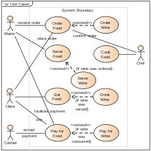
In software and systems engineering, the phrase use case is a polyseme with two senses:
- A usage scenario for a piece of software; often used in the plural to suggest situations where a piece of software may be useful.
- A potential scenario in which a system receives an external request and responds to it.
A modeling language is any artificial language that can be used to express data, information or knowledge or systems in a structure that is defined by a consistent set of rules. The rules are used for interpretation of the meaning of components in the structure of a programming language.

In systems engineering and software engineering, requirements analysis focuses on the tasks that determine the needs or conditions to meet the new or altered product or project, taking account of the possibly conflicting requirements of the various stakeholders, analyzing, documenting, validating, and managing software or system requirements.

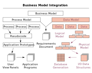
In systems engineering, information systems and software engineering, the systems development life cycle (SDLC), also referred to as the application development life cycle, is a process for planning, creating, testing, and deploying an information system. The SDLC concept applies to a range of hardware and software configurations, as a system can be composed of hardware only, software only, or a combination of both. There are usually six stages in this cycle: requirement analysis, design, development and testing, implementation, documentation, and evaluation.

Computer-aided software engineering (CASE) is a domain of software tools used to design and implement applications. CASE tools are similar to and are partly inspired by computer-aided design (CAD) tools used for designing hardware products. CASE tools are intended to help develop high-quality, defect-free, and maintainable software. CASE software was often associated with methods for the development of information systems together with automated tools that could be used in the software development process.

Data modeling in software engineering is the process of creating a data model for an information system by applying certain formal techniques. It may be applied as part of broader Model-driven engineering (MDE) concept.

Business process modeling (BPM), mainly used in business process management; software development, or systems engineering, is the action of capturing and representing processes of an enterprise, so that the current business processes may be analyzed, applied securely and consistently, improved, and automated. BPM is typically orchestrated by business analysts, leveraging their expertise in modeling practices. Subject matter experts, equipped with specialized knowledge of the processes being modeled, often collaborate within these teams. Alternatively, process models can be directly derived from digital traces within IT systems, such as event logs, utilizing process mining tools.
A data-flow diagram is a way of representing a flow of data through a process or a system. The DFD also provides information about the outputs and inputs of each entity and the process itself. A data-flow diagram has no control flow — there are no decision rules and no loops. Specific operations based on the data can be represented by a flowchart.
The term conceptual model refers to any model that is formed after a conceptualization or generalization process. Conceptual models are often abstractions of things in the real world, whether physical or social. Semantic studies are relevant to various stages of concept formation. Semantics is fundamentally a study of concepts, the meaning that thinking beings give to various elements of their experience.
Object-oriented analysis and design (OOAD) is a technical approach for analyzing and designing an application, system, or business by applying object-oriented programming, as well as using visual modeling throughout the software development process to guide stakeholder communication and product quality.
Object-oriented design (OOD) is the process of planning a system of interacting objects to solve a software problem. It is a method for software design. By defining classes and their functionality for their children, each object can run the same implementation of the class with its state.

In software engineering, structured analysis (SA) and structured design (SD) are methods for analyzing business requirements and developing specifications for converting practices into computer programs, hardware configurations, and related manual procedures.

Misuse case is a business process modeling tool used in the software development industry. The term Misuse Case or mis-use case is derived from and is the inverse of use case. The term was first used in the 1990s by Guttorm Sindre of the Norwegian University of Science and Technology, and Andreas L. Opdahl of the University of Bergen, Norway. It describes the process of executing a malicious act against a system, while use case can be used to describe any action taken by the system.
Enterprise engineering is the body of knowledge, principles, and practices used to design all or part of an enterprise. An enterprise is a complex socio-technical system that comprises people, information, and technology that interact with each other and their environment in support of a common mission. One definition is: "an enterprise life-cycle oriented discipline for the identification, design, and implementation of enterprises and their continuous evolution", supported by enterprise modelling. The discipline examines each aspect of the enterprise, including business processes, information flows, material flows, and organizational structure. Enterprise engineering may focus on the design of the enterprise as a whole, or on the design and integration of certain business components.
A goal model is an element of requirements engineering that may also be used more widely in business analysis. Related elements include stakeholder analysis, context analysis, and scenarios, among other business and technical areas.
UML is a modeling language used by software developers. UML can be used to develop diagrams and provide users (programmers) with ready-to-use, expressive modeling examples. Some UML tools generate program language code from UML. UML can be used for modeling a system independent of a platform language. UML is a graphical language for visualizing, specifying, constructing, and documenting information about software-intensive systems. UML gives a standard way to write a system model, covering conceptual ideas. With an understanding of modeling, the use and application of UML can make the software development process more efficient.
Software architecture description is the set of practices for expressing, communicating and analysing software architectures, and the result of applying such practices through a work product expressing a software architecture.