A viscometer (also called viscosimeter) is an instrument used to measure the viscosity of a fluid. For liquids with viscosities which vary with flow conditions, an instrument called a rheometer is used. Thus, a rheometer can be considered as a special type of viscometer.[1] Viscometers can measure only constant viscosity, that is, viscosity that does not change with flow conditions.
In general, either the fluid remains stationary and an object moves through it, or the object is stationary and the fluid moves past it. The drag caused by relative motion of the fluid and a surface is a measure of the viscosity. The flow conditions must have a sufficiently small value of Reynolds number for there to be laminar flow.
At 20°C, the dynamic viscosity (kinematic viscosity × density) of water is 1.0038mPa·s and its kinematic viscosity (product of flow time × factor) is 1.0022mm2/s. These values are used for calibrating certain types of viscometers.
Standard laboratory viscometers for liquids
Ostwald viscometers measure the viscosity of a fluid with a known density.
U-tube viscometers
These devices are also known as glass capillary viscometers or Ostwald viscometers, named after Wilhelm Ostwald. Another version is the Ubbelohde viscometer, which consists of a U-shaped glass tube held vertically in a controlled temperature bath. In one arm of the U is a vertical section of precise narrow bore (the capillary). Above there is a bulb, with it is another bulb lower down on the other arm. In use, liquid is drawn into the upper bulb by suction, then allowed to flow down through the capillary into the lower bulb. Two marks (one above and one below the upper bulb) indicate a known volume. The time taken for the level of the liquid to pass between these marks is proportional to the kinematic viscosity. The calibration can be done using a fluid of known properties. Most commercial units are provided with a conversion factor.
The time required for the test liquid to flow through a capillary of a known diameter of a certain factor between two marked points is measured. By multiplying the time taken by the factor of the viscometer, the kinematic viscosity is obtained.
Such viscometers can be classified as direct-flow or reverse-flow. Reverse-flow viscometers have the reservoir above the markings, and direct-flow are those with the reservoir below the markings. Such classifications exist so that the level can be determined even when opaque or staining liquids are measured, otherwise the liquid will cover the markings and make it impossible to gauge the time the level passes the mark. This also allows the viscometer to have more than 1 set of marks to allow for an immediate timing of the time it takes to reach the 3rd mark[clarify], therefore yielding 2 timings and allowing subsequent calculation of determinability to ensure accurate results. The use of two timings in one viscometer in a single run is only possible if the sample being measured has Newtonian properties. Otherwise the change in driving head, which in turn changes the shear rate, will produce a different viscosity for the two bulbs.
Falling-sphere viscometers
Creeping flow past a sphere
Stokes' law is the basis of the falling-sphere viscometer, in which the fluid is stationary in a vertical glass tube. A sphere of known size and density is allowed to descend through the liquid. If correctly selected, it reaches terminal velocity, which can be measured by the time it takes to pass two marks on the tube. Electronic sensing can be used for opaque fluids. Knowing the terminal velocity, the size and density of the sphere, and the density of the liquid, Stokes' law can be used to calculate the viscosity of the fluid. A series of steel ball bearings of different diameter are normally used in the classic experiment to improve the accuracy of the calculation. The school experiment uses glycerol as the fluid, and the technique is used industrially to check the viscosity of fluids used in processes. It includes many different oils and polymer liquids such as solutions[clarify].
If the particles are falling in the viscous fluid by their own weight, then a terminal velocity, also known as the settling velocity, is reached when this frictional force combined with the buoyant force exactly balance the gravitational force. The resulting settling velocity (or terminal velocity) is given by
where:
Vs is the particle settling velocity (m/s), vertically downwards if ρp>ρf, upwards if ρp<ρf,
A limiting factor on the validity of this result is the roughness of the sphere being used.
A modification of the straight falling-sphere viscometer is a rolling-ball viscometer, which times a ball rolling down a slope whilst immersed in the test fluid. This can be further improved by using a patented V plate, which increases the number of rotations to distance traveled, allowing smaller, more portable devices. The controlled rolling motion of the ball avoids turbulences in the fluid, which would otherwise occur with a falling ball.[2] This type of device is also suitable for ship board use.[why?]
Falling-piston viscometer
Also known as the Norcross viscometer after its inventor, Austin Norcross. The principle of viscosity measurement in this rugged and sensitive industrial device is based on a piston and cylinder assembly. The piston is periodically raised by an air lifting mechanism, drawing the material being measured down through the clearance (gap) between the piston and the wall of the cylinder into the space formed below the piston as it is raised. The assembly is then typically held up for a few seconds, then allowed to fall by gravity, expelling the sample out through the same path that it entered, creating a shearing effect on the measured liquid, which makes this viscometer particularly sensitive and good for measuring certain thixotropic liquids. The time of fall is a measure of viscosity, with the clearance between the piston and inside of the cylinder forming the measuring orifice. The viscosity controller measures the time of fall (time-of-fall seconds being the measure of viscosity) and displays the resulting viscosity value. The controller can calibrate the time-of-fall value to cup seconds (known as efflux cup), Saybolt universal second (SUS) or centipoise.
Industrial use is popular due to simplicity, repeatability, low maintenance and longevity. This type of measurement is not affected by flow rate or external vibrations. The principle of operation can be adapted for many different conditions, making it ideal for process control environments.
Oscillating-piston viscometer
Sometimes referred to as electromagnetic viscometer or EMV viscometer, was invented at Cambridge Viscosity (Formally Cambridge Applied Systems) in 1986. The sensor (see figure below) comprises a measurement chamber and magnetically influenced piston. Measurements are taken whereby a sample is first introduced into the thermally controlled measurement chamber where the piston resides. Electronics drive the piston into oscillatory motion within the measurement chamber with a controlled magnetic field. A shear stress is imposed on the liquid (or gas) due to the piston travel, and the viscosity is determined by measuring the travel time of the piston. The construction parameters for the annular spacing between the piston and measurement chamber, the strength of the electromagnetic field, and the travel distance of the piston are used to calculate the viscosity according to Newton's law of viscosity.
Schematic view of oscillating-piston viscometer
The oscillating-piston viscometer technology has been adapted for small-sample viscosity and micro-sample viscosity testing in laboratory applications. It has also been adapted to high-pressure viscosity and high-temperature viscosity measurements in both laboratory and process environments. The viscosity sensors have been scaled for a wide range of industrial applications, such as small-size viscometers for use in compressors and engines, flow-through viscometers for dip coating processes, in-line viscometers for use in refineries, and hundreds of other applications. Improvements in sensitivity from modern electronics, is stimulating a growth in oscillating-piston viscometer popularity with academic laboratories exploring gas viscosity.
Vibrational viscometers
Vibrational viscometers date back to the 1950s Bendix instrument, which is of a class that operates by measuring the damping of an oscillating electromechanical resonator immersed in a fluid whose viscosity is to be determined. The resonator generally oscillates in torsion or transversely (as a cantilever beam or tuning fork). The higher the viscosity, the larger the damping imposed on the resonator. The resonator's damping may be measured by one of several methods:
Measuring the power input necessary to keep the oscillator vibrating at a constant amplitude. The higher the viscosity, the more power is needed to maintain the amplitude of oscillation.
Measuring the decay time of the oscillation once the excitation is switched off. The higher the viscosity, the faster the signal decays.
Measuring the frequency of the resonator as a function of phase angle between excitation and response waveforms. The higher the viscosity, the larger the frequency change for a given phase change.
The vibrational instrument also suffers from a lack of a defined shear field, which makes it unsuited to measuring the viscosity of a fluid whose flow behaviour is not known beforehand.
Vibrating viscometers are rugged industrial systems used to measure viscosity in the process condition. The active part of the sensor is a vibrating rod. The vibration amplitude varies according to the viscosity of the fluid in which the rod is immersed. These viscosity meters are suitable for measuring clogging fluid and high-viscosity fluids, including those with fibers (up to 1000Pa·s). Currently, many industries around the world consider these viscometers to be the most efficient system with which to measure the viscosities of a wide range of fluids; by contrast, rotational viscometers require more maintenance, are unable to measure clogging fluid, and require frequent calibration after intensive use. Vibrating viscometers have no moving parts, no weak parts and the sensitive part is typically small. Even very basic or acidic fluids can be measured by adding a protective coating, such as enamel, or by changing the material of the sensor to a material such as 316Lstainless steel. Vibrating viscometers are the most widely used inline instrument to monitor the viscosity of the process fluid in tanks, and pipes.
Quartz viscometer
The quartz viscometer is a special type of vibrational viscometer. Here, an oscillating quartz crystal is immersed into a fluid and the specific influence on the oscillating behavior defines the viscosity. The principle of quartz viscosimetry is based on the idea of W.P. Mason. The basic concept is the application of a piezoelectric crystal for the determination of viscosity. The high-frequency electric field that is applied to the oscillator causes a movement of the sensor and results in the shearing of the fluid. The movement of the sensor is then influenced by the external forces (the shear stress) of the fluid, which affects the electrical response of the sensor.[3] The calibration procedure as a pre-condition of viscosity determination by means of a quartz crystal goes back to B. Bode, who facilitated the detailed analysis of the electrical and mechanical transmission behavior of the oscillating system.[4] On the basis of this calibration, the quartz viscosimeter was developed which allows continuous viscosity determination in resting and flowing liquids.[5]
Quartz crystal microbalance
The quartz crystal microbalance functions as a vibrational viscometer by the piezoelectric properties inherent in quartz to perform measurements of conductance spectra of liquids and thin films exposed to the surface of the crystal.[6] From these spectra, frequency shifts and a broadening of the peaks for the resonant and overtone frequencies of the quartz crystal are tracked and used to determine changes in mass as well as the viscosity, shear modulus, and other viscoelastic properties of the liquid or thin film. One benefit of using the quartz crystal microbalance to measure viscosity is the small amount of sample required for obtaining an accurate measurement. However, due to the dependence viscoelastic properties on the sample preparation techniques and thickness of the film or bulk liquid, there can be errors up to 10% in measurements in viscosity between samples.[6]
An interesting technique to measure the viscosity of a liquid using a quartz crystal microbalance which improves the consistency of measurements uses a drop method.[7][8] Instead of creating a thin film or submerging the quartz crystal in a liquid, a single drop of the fluid of interest is dropped on the surface of the crystal. The viscosity is extracted from the shift in the frequency data using the following equation
where is the resonant frequency, is the density of the fluid, is the shear modulus of the quartz, and is the density of the quartz.[8] An extension of this technique corrects the shift in the resonant frequency by the size of the drop deposited on the quartz crystal.[7]
Rotational viscometers
Rotational viscometers use the idea that the torque required to rotate an object in a fluid is a function of the viscosity of that fluid. They measure the torque required to rotate a disk or bob in a fluid at a known speed.
"Cup and bob" viscometers work by defining the exact volume of a sample to be sheared within a test cell; the torque required to achieve a certain rotational speed is measured and plotted. There are two classical geometries in "cup and bob" viscometers, known as either the "Couette" or "Searle" systems, distinguished by whether the cup or bob rotates. The rotating cup is preferred in some cases because it reduces the onset of Taylor vortices at very high shear rates, but the rotating bob is more commonly used, as the instrument design can be more flexible for other geometries as well.
"Cone and plate" viscometers use a narrow-angled cone in close proximity to a flat plate. With this system, the shear rate between the geometries is constant at any given rotational speed. The viscosity can easily be calculated from shear stress (from the torque) and shear rate (from the angular velocity).
If a test with any geometries runs through a table of several shear rates or stresses, the data can be used to plot a flow curve, that is a graph of viscosity vs shear rate. If the above test is carried out slowly enough for the measured value (shear stress if rate is being controlled, or conversely) to reach a steady value at each step, the data is said to be at "equilibrium", and the graph is then an "equilibrium flow curve". This is preferable over non-equilibrium measurements, as the data can usually be replicated across multiple other instruments or with other geometries.
Calculation of shear rate and shear stress form factors
Rheometers and viscometers work with torque and angular velocity. Since viscosity is normally considered in terms of shear stress and shear rates, a method is needed to convert from "instrument numbers" to "rheology numbers". Each measuring system used in an instrument has its associated "form factors" to convert torque to shear stress and to convert angular velocity to shear rate.
We will call the shear stress form factor C1 and the shear rate factor C2.
shear stress = torque ÷ C1.
shear rate = C2 × angular velocity.
For some measuring systems such as parallel plates, the user can set the gap between the measuring systems. In this case the equation used is
shear rate = C2 × angular velocity / gap.
viscosity = shear stress / shear rate.
The following sections show how the form factors are calculated for each measuring system.
Cone and plate
where
r is the radius of the cone,
θ is the cone angle in radians.
Parallel plates
where r is the radius of the plate.
Note: The shear stress varies across the radius for a parallel plate. The above formula refers to the 3/4 radius position if the test sample is Newtonian.
Coaxial cylinders
where:
ra = (ri + ro)/2 is the average radius,
ri is the inner radius,
ro is the outer radius,
H is the height of cylinder.
Note: C1 takes the shear stress as that occurring at an average radius ra.
Measuring principle of the electromagnetically spinning-sphere viscometer
The EMS viscometer measures the viscosity of liquids through observation of the rotation of a sphere driven by electromagnetic interaction: Two magnets attached to a rotor create a rotating magnetic field. The sample ③ to be measured is in a small test tube ②. Inside the tube is an aluminium sphere ④. The tube is located in a temperature-controlled chamber ① and set such that the sphere is situated in the centre of the two magnets.
The rotating magnetic field induces eddy currents in the sphere. The resulting Lorentz interaction between the magnetic field and these eddy currents generate torque that rotates the sphere. The rotational speed of the sphere depends on the rotational velocity of the magnetic field, the magnitude of the magnetic field and the viscosity of the sample around the sphere. The motion of the sphere is monitored by a video camera ⑤ located below the cell. The torque applied to the sphere is proportional to the difference in the angular velocity of the magnetic field ΩB and the one of the sphere ΩS. There is thus a linear relationship between (ΩB − ΩS)/ΩS and the viscosity of the liquid.
This new measuring principle was developed by Sakai et al. at the University of Tokyo. The EMS viscometer distinguishes itself from other rotational viscometers by three main characteristics:
All parts of the viscometer that come in direct contact with the sample are disposable and inexpensive.
The measurements are performed in a sealed sample vessel.
The EMS viscometer requires only very small sample quantities (0.3mL).
Stabinger viscometer
By modifying the classic Couette-type rotational viscometer, it is possible to combine the accuracy of kinematic viscosity determination with a wide measuring range.
The outer cylinder of the Stabinger viscometer is a sample-filled tube that rotates at constant speed in a temperature-controlled copper housing. The hollow internal cylinder – shaped as a conical rotor – is centered within the sample by hydrodynamic lubrication[9] effects and centrifugal forces. In this way all bearing friction, an inevitable factor in most rotational devices, is fully avoided. The rotating fluid's shear forces drive the rotor, while a magnet inside the rotor forms an eddy current brake with the surrounding copper housing. An equilibrium rotor speed is established between driving and retarding forces, which is an unambiguous measure of the dynamic viscosity. The speed and torque measurement is implemented without direct contact by a Hall-effect sensor counting the frequency of the rotating magnetic field. This allows a highly precise torque resolution of 50pN·m and a wide measuring range from 0.2 to 30,000mPa·s with a single measuring system. A built-in density measurement based on the oscillating U-tube principle allows the determination of kinematic viscosity from the measured dynamic viscosity employing the relation
where:
ν is the kinematic viscosity (mm2/s),
η is the dynamic viscosity (mPa·s),
ρ is the density (g/cm3).
Bubble viscometer
Bubble viscometers are used to quickly determine kinematic viscosity of known liquids such as resins and varnishes. The time required for an air bubble to rise is directly proportional to the viscosity of the liquid, so the faster the bubble rises, the lower the viscosity. The alphabetical-comparison method uses 4 sets of lettered reference tubes, A5 through Z10, of known viscosity to cover a viscosity range from 0.005 to 1,000 stokes. The direct-time method uses a single 3-line times tube for determining the "bubble seconds", which may then be converted to stokes.[10]
This method is considerably accurate, but the measurements can vary due to variances in buoyancy because of the changing in shape of the bubble in the tube.[10] However, this does not cause any sort of serious miscalculation.
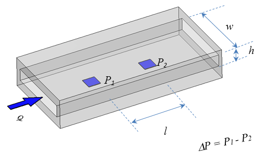
Rectangular-slit viscometer
The basic design of a rectangular-slit viscometer/rheometer consists of a rectangular-slit channel with uniform cross-sectional area. A test liquid is pumped at a constant flow rate through this channel. Multiple pressure sensors flush-mounted at linear distances along the stream-wise direction measure pressure drop as depicted in the figure:
Measuring principle: The slit viscometer/rheometer is based on the fundamental principle that a viscous liquid resists flow, exhibiting a decreasing pressure along the length of the slit. The pressure decrease or drop (∆P) is correlated with the shear stress at the wall boundary. The apparent shear rate is directly related to the flow rate and the dimension of the slit. The apparent shear rate, the shear stress, and the apparent viscosity are calculated:
where
is the apparent shear rate (s−1),
σ is the shear stress (Pa),
ηa is the apparent viscosity (Pa·s),
∆P is the pressure difference between the leading pressure sensor and the last pressure sensor (Pa),
Q is the flow rate (ml/s),
w is the width of the flow channel (mm),
h is the depth of the flow channel (mm),
l is the distance between the leading pressure sensor and the last pressure sensor (mm).
To determine the viscosity of a liquid, the liquid sample is pumped through the slit channel at a constant flow rate, and the pressure drop is measured. Following these equations, the apparent viscosity is calculated for the apparent shear rate. For a Newtonian liquid, the apparent viscosity is the same as the true viscosity, and the single shear-rate measurement is sufficient. For non-Newtonian liquids, the apparent viscosity is not true viscosity. In order to obtain true viscosity, the apparent viscosities are measured at multiple apparent shear rates. Then true viscosities η at various shear rates are calculated using Weissenberg–Rabinowitsch–Mooney correction factor:[12]
The calculated true viscosity is the same as the cone and plate values at the same shear rate.
A modified version of the rectangular-slit viscometer/rheometer can also be used to determine apparent extensional viscosity.
Krebs Viscometer
The Krebs Viscometer uses a digital graph and a small sidearm spindle to measure the viscosity of a fluid. It is mostly used in the paint industry.
Miscellaneous viscometer types
Other viscometer types use balls or other objects. Viscometers that can characterize non-Newtonian fluids are usually called rheometers or plastometers. Some instruments like capillary or VROC® viscometers can measure both Newtonian and non-Newtonian fluids.[13][14]
In the I.C.I "Oscar" viscometer, a sealed can of fluid was oscillated torsionally, and by clever measurement techniques it was possible to measure both viscosity and elasticity in the sample.
The Marsh funnel viscometer measures viscosity from the time (efflux time) it takes a known volume of liquid to flow from the base of a cone through a short tube. This is similar in principle to the flow cups (efflux cups) like the Ford, Zahn and Shell cups which use different shapes to the cone and various nozzle sizes. The measurements can be done according to ISO 2431, ASTM D1200 - 10 or DIN 53411. [15]
The flexible-blade rheometer improves the accuracy of measurements for the lower-viscosity liquids utilizing the subtle changes in the flow field due to the flexibility of the moving or stationary blade (sometimes called wing or single-side-clamped cantilever).
Rheology is the study of the flow of matter, primarily in a fluid state, but also as "soft solids" or solids under conditions in which they respond with plastic flow rather than deforming elastically in response to an applied force. Rheology is a branch of physics, and it is the science that deals with the deformation and flow of materials, both solids and liquids.
Flow measurement is the quantification of bulk fluid movement. Flow can be measured using devices called flowmeters in various ways. The common types of flowmeters with industrial applications are listed below:
A Newtonian fluid is a fluid in which the viscous stresses arising from its flow are at every point linearly correlated to the local strain rate — the rate of change of its deformation over time. Stresses are proportional to the rate of change of the fluid's velocity vector.
Shear stress is the component of stress coplanar with a material cross section. It arises from the shear force, the component of force vector parallel to the material cross section. Normal stress, on the other hand, arises from the force vector component perpendicular to the material cross section on which it acts.
In continuum mechanics, a power-law fluid, or the Ostwald–de Waele relationship, is a type of generalized Newtonian fluid for which the shear stress, τ, is given by
Hemorheology, also spelled haemorheology, or blood rheology, is the study of flow properties of blood and its elements of plasma and cells. Proper tissue perfusion can occur only when blood's rheological properties are within certain levels. Alterations of these properties play significant roles in disease processes. Blood viscosity is determined by plasma viscosity, hematocrit and mechanical properties of red blood cells. Red blood cells have unique mechanical behavior, which can be discussed under the terms erythrocyte deformability and erythrocyte aggregation. Because of that, blood behaves as a non-Newtonian fluid. As such, the viscosity of blood varies with shear rate. Blood becomes less viscous at high shear rates like those experienced with increased flow such as during exercise or in peak-systole. Therefore, blood is a shear-thinning fluid. Contrarily, blood viscosity increases when shear rate goes down with increased vessel diameters or with low flow, such as downstream from an obstruction or in diastole. Blood viscosity also increases with increases in red cell aggregability.
In materials science and continuum mechanics, viscoelasticity is the property of materials that exhibit both viscous and elastic characteristics when undergoing deformation. Viscous materials, like water, resist shear flow and strain linearly with time when a stress is applied. Elastic materials strain when stretched and immediately return to their original state once the stress is removed.
A quartz crystal microbalance (QCM) measures a mass variation per unit area by measuring the change in frequency of a quartz crystal resonator. The resonance is disturbed by the addition or removal of a small mass due to oxide growth/decay or film deposition at the surface of the acoustic resonator. The QCM can be used under vacuum, in gas phase and more recently in liquid environments. It is useful for monitoring the rate of deposition in thin-film deposition systems under vacuum. In liquid, it is highly effective at determining the affinity of molecules to surfaces functionalized with recognition sites. Larger entities such as viruses or polymers are investigated as well. QCM has also been used to investigate interactions between biomolecules. Frequency measurements are easily made to high precision ; hence, it is easy to measure mass densities down to a level of below 1 μg/cm2. In addition to measuring the frequency, the dissipation factor is often measured to help analysis. The dissipation factor is the inverse quality factor of the resonance, Q−1 = w/fr ; it quantifies the damping in the system and is related to the sample's viscoelastic properties.
In physics, shear rate is the rate at which a progressive shear strain is applied to some material, causing shearing to the material.
A rheometer is a laboratory device used to measure the way in which a viscous fluid flows in response to applied forces. It is used for those fluids which cannot be defined by a single value of viscosity and therefore require more parameters to be set and measured than is the case for a viscometer. It measures the rheology of the fluid.
Fluid mechanics is the branch of physics concerned with the mechanics of fluids and the forces on them. It has applications in a wide range of disciplines, including mechanical, aerospace, civil, chemical, and biomedical engineering, as well as geophysics, oceanography, meteorology, astrophysics, and biology.
Volume viscosity is a material property relevant for characterizing fluid flow. Common symbols are or . It has dimensions, and the corresponding SI unit is the pascal-second (Pa·s).
An acoustic rheometer is a device used to measure the rheological properties of fluids, such as viscosity and elasticity, by utilizing sound waves. It works by generating acoustic waves in the fluid and analyzing the changes in the wave propagation caused by the fluid's rheological behavior. An acoustic rheometer uses a piezo-electric crystal to generate the acoustic waves, applying an oscillating extensional stress to the system. System response can be interpreted in terms of extensional rheology.
Brookfield Engineering is an engineering and manufacturing company with headquarters in Middleboro, Massachusetts. It is a subsidiary of the conglomerate Ametek. Its product line includes laboratory viscometers, rheometers, texture analyzers, and powder flow testers as well as in-line process instrumentation. These instruments are used by research, design, and process control departments.
In fluid mechanics, apparent viscosity is the shear stress applied to a fluid divided by the shear rate:
The viscosity of a fluid is a measure of its resistance to deformation at a given rate. For liquids, it corresponds to the informal concept of "thickness": for example, syrup has a higher viscosity than water. Viscosity is defined scientifically as a force multiplied by a time divided by an area. Thus its SI units are newton-seconds per square meter, or pascal-seconds.
The viscous stress tensor is a tensor used in continuum mechanics to model the part of the stress at a point within some material that can be attributed to the strain rate, the rate at which it is deforming around that point.
Biofluid dynamics may be considered as the discipline of biological engineering or biomedical engineering in which the fundamental principles of fluid dynamics are used to explain the mechanisms of biological flows and their interrelationships with physiological processes, in health and in diseases/disorder. It can be considered as the conjuncture of mechanical engineering and biological engineering. It spans from cells to organs, covering diverse aspects of the functionality of systemic physiology, including cardiovascular, respiratory, reproductive, urinary, musculoskeletal and neurological systems etc. Biofluid dynamics and its simulations in computational fluid dynamics (CFD) apply to both internal as well as external flows. Internal flows such as cardiovascular blood flow and respiratory airflow, and external flows such as flying and aquatic locomotion. Biological fluid Dynamics involves the study of the motion of biological fluids. It can be either circulatory system or respiratory systems. Understanding the circulatory system is one of the major areas of research. The respiratory system is very closely linked to the circulatory system and is very complex to study and understand. The study of Biofluid Dynamics is also directed towards finding solutions to some of the human body related diseases and disorders. The usefulness of the subject can also be understood by seeing the use of Biofluid Dynamics in the areas of physiology in order to explain how living things work and about their motions, in developing an understanding of the origins and development of various diseases related to human body and diagnosing them, in finding the cure for the diseases related to cardiovascular and pulmonary systems.
Capillary breakup rheometry is an experimental technique used to assess the extensional rheological response of low viscous fluids. Unlike most shear and extensional rheometers, this technique does not involve active stretch or measurement of stress or strain but exploits only surface tension to create a uniaxial extensional flow. Hence, although it is common practice to use the name rheometer, capillary breakup techniques should be better addressed to as indexers.
Squeeze flow is a type of flow in which a material is pressed out or deformed between two parallel plates or objects. First explored in 1874 by Josef Stefan, squeeze flow describes the outward movement of a droplet of material, its area of contact with the plate surfaces, and the effects of internal and external factors such as temperature, viscoelasticity, and heterogeneity of the material. Several squeeze flow models exist to describe Newtonian and non-Newtonian fluids undergoing squeeze flow under various geometries and conditions. Numerous applications across scientific and engineering disciplines including rheometry, welding engineering, and materials science provide examples of squeeze flow in practical use.
References
↑ Barnes, H. A.; Hutton, J. F.; Walters, K. (1989). An introduction to rheology (5. impr.ed.). Amsterdam: Elsevier. p.12. ISBN978-0-444-87140-4.
↑ W. P. Mason, M. Hill: Measurement of the viscosity and shear elasticity of liquids by means of a torsionally vibrating crystal; Transactions of the ASME. In: Journal of Lubricating Technology. Band 69, 1947, S. 359–370.
↑ Berthold Bode: Entwicklung eines Quarzviskosimeters für Messungen bei hohen Drücken. Dissertation der TU Clausthal, 1984.
1 2 Bai, Qingsong; Hu, Jianguo; Huang, Xianhe; Huang, Hongyuan (2016). "Using QCM for field measurement of liquid viscosities in a novel mass-sensitivity-base method". 2016 IEEE International Frequency Control Symposium (IFCS). New Orleans, LA, USA: IEEE. pp.1–3. doi:10.1109/FCS.2016.7546819. ISBN9781509020911. S2CID1584926.
↑ Beitz, W. and Küttner, K.-H., English edition by Davies, B. J., translation by Shields, M. J. (1994). Dubbel Handbook of Mechanical Engineering. London: Springer-Verlag Ltd., p. F89.
This page is based on this Wikipedia article Text is available under the CC BY-SA 4.0 license; additional terms may apply. Images, videos and audio are available under their respective licenses.