Weld quality assurance

Last updated

Weld quality assurance is the use of technological methods and actions to test or assure the quality of welds, and secondarily to confirm the presence, location and coverage of welds.[ original research? ] In manufacturing, welds are used to join two or more metal surfaces. Because these connections may encounter loads and fatigue during product lifetime, there is a chance they may fail if not created to proper specification.

Contents

Weld testing and analysis

Methods of weld testing and analysis are used to assure the quality and correctness of the weld after it is completed. This term generally refers to testing and analysis focused on the quality and strength of the weld but may refer to technological actions to check for the presence, position, and extent of welds.[ citation needed ] These are divided into destructive and non-destructive methods. A few examples of destructive testing include macro etch testing, fillet-weld break tests, transverse tension tests, and guided bend tests. [1] [ unreliable source? ] Other destructive methods include acid etch testing, back bend testing, tensile strength break testing, nick break testing, and free bend testing. [2] [ unreliable source? ] Non-destructive methods include fluorescent penetrate tests, magnaflux tests, eddy current (electromagnetic) tests, hydrostatic testing, tests using magnetic particles, X-rays and gamma ray-based methods, and acoustic emission techniques. [2] Other methods include ferrite and hardness testing. [2]

Imaging-based methods

Industrial Radiography

X-ray-based weld inspection may be manual, performed by an inspector on X-ray-based images or video, or automated using machine vision. [3] Gamma Rays can also be used

Visible light imaging

Inspection may be manual, conducted by an inspector using imaging equipment, or automated using machine vision.[ citation needed ] Since the similarity of materials between weld and workpiece, and between good and defective areas, provides little inherent contrast, the latter usually requires methods other than simple imaging.[ citation needed ]

One (destructive) method involves the microscopic analysis of a weld cross-section. [4] [ unreliable source? ]

Ultrasonic- and acoustic-based methods

Ultrasonic testing uses the principle that a gap in the weld changes the propagation of ultrasonic sound through the metal. One common method uses single-probe ultrasonic testing involving operator interpretation of an oscilloscope-type screen. [5] Another senses using a 2D array of ultrasonic sensors. [5] Conventional, phased array and time of flight diffraction (TOFD) methods can be combined into the same piece of test equipment. [6]

Acoustic emission methods monitor for the sound created by the loading or flexing of the weld. [2]

Peel testing of spot welds

This method includes tearing the weld apart and measuring the size of the remaining weld. [5]

Weld monitoring

Weld monitoring methods ensure the weld's quality and correctness during welding. The term is generally applied to automated monitoring for weld-quality purposes and secondarily for process-control purposes such as vision-based robot guidance.[ citation needed ] Visual weld monitoring is also performed during the welding process.[ citation needed ]

On vehicular applications, weld monitoring aims to enable improvements in the quality, durability, and safety of vehicles – with cost savings in the avoidance of recalls to fix the large proportion of systemic quality problems that arise from suboptimal welding.[ citation needed ] Quality monitoring of automatic welding can save production downtime and reduce the need for product reworking and recall.

Industrial monitoring systems encourage high production rates and reduce scrap costs. [7]

Inline coherent imaging

Inline coherent imaging (ICI) is a recently developed interferometric technique based on optical coherence tomography [8] that is used for quality assurance of keyhole laser beam welding, a welding method that is gaining popularity in a variety of industries. ICI aims a low-powered broadband light source through the same optical path as the primary welding laser. The beam enters the keyhole of the weld and is reflected back into the head optics by the bottom of the keyhole. An interference pattern is produced by combining the reflected light with a separate beam that has traveled through a path of a known distance. This interference pattern is then analyzed to obtain a precise measurement of the depth of the keyhole. Because these measurements are acquired in real-time, ICI can also be used to control the laser penetration depth by using the depth measurement in a feedback loop that modulates the laser's output power.

Transient thermal analysis method

Transient thermal analysis is used for range of weld optimization tasks. [9]

Signature image processing method

A WeldPrint analyzer, which uses SIP for the industrial analysis of weld quality Weldprintbox.jpg
A WeldPrint analyzer, which uses SIP for the industrial analysis of weld quality

Signature image processing (SIP) is a technology for analyzing electrical data collected from welding processes. Acceptable welding requires exact conditions; variations in conditions can render a weld unacceptable. SIP allows the identification of welding faults in real time, measures the stability of welding processes, and enables the optimization of welding processes.

Development

The idea of using electrical data analyzed by algorithms to assess the quality of the welds produced in robotic manufacturing emerged in 1995 from research by Associate Professor Stephen Simpson at the University of Sydney on the complex physical phenomena that occur in welding arcs. Simpson realized that a way of determining the quality of a weld could be developed without a definitive understanding of those phenomena. [10] [11] [12] The development involved:

  1. a method for handling sampled data blocks by treating them as phase-space portrait signatures with appropriate image processing. Typically, one second's worth of sampled welding voltage and current data are collected from GMAW pulse or short arc welding processes. The data is converted to a 2D histogram, and signal-processing operations such as image smoothing are performed. [13]
  2. a technique for analyzing welding signatures based on statistical methods from the social sciences, such as principal component analysis. The relationship between the welding voltage and the current reflects the state of the welding process, and the signature image includes this information. Comparing signatures quantitatively using principal component analysis allows for the spread of signature images, enabling faults to be detected [14] and identified [15] The system includes algorithms and mathematics appropriate for real-time welding analysis on personal computers, and the multidimensional optimization of fault-detection performance using experimental welding data. [16] Comparing signature images from moment to moment in a weld provides a useful estimate of how stable the welding process is. [17] [18] "Through-the-arc" sensing, by comparing signature images when the physical parameters of the process change, leads to quantitative estimates—for example, of the position of the weld bead. [19]

Unlike systems that log information for later study or use X-rays or ultrasound to check samples, SIP technology looks at the electrical signal and detects faults when they occur. [20] Data blocks of 4,000 points of electrical data are collected four times a second and converted to signature images. After image processing operations, statistical analyses of the signatures provide a quantitative assessment of the welding process, revealing its stability and reproducibility and providing fault detection and process diagnostics. [14] A similar approach, using voltage-current histograms and a simplified statistical measure of distance between signature images, has been evaluated for tungsten inert gas (TIG) welding by researchers from Osaka University. [21] [22]

Industrial application

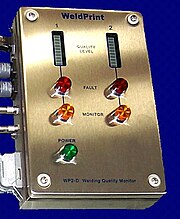
SIP provides the basis for the WeldPrint system, which consists of a front-end interface and software based on the SIP engine and relies on electrical signals alone. It is designed to be non-intrusive and sufficiently robust to withstand harsh industrial welding environments. The first major purchaser of the technology, GM Holden [23] [24] [25] provided feedback that allowed the system to be refined in ways that increased its industrial and commercial value. Improvements in the algorithms, including multiple parameter optimization with a server network, have led to an order-of-magnitude improvement in fault-detection performance over the past five years.[ when? ]

The technology in use on the shop floor of Melbourne firm Unidrive, which used WeldPrint to monitor the quality of steering-column component welds in more than half a million Australian vehicles in the period 2001-06 SIP weld analysis of driveshafts.jpg
The technology in use on the shop floor of Melbourne firm Unidrive, which used WeldPrint to monitor the quality of steering-column component welds in more than half a million Australian vehicles in the period 2001–06

WeldPrint for arc welding became available in mid-2001. About 70 units have been deployed since 2001, about 90% used on the shop floors of automotive manufacturing companies and their suppliers. Industrial users include Lear (UK), Unidrive, GM Holden, Air International and QTB Automotive (Australia). Units have been leased to Australian companies such as Rheem, Dux, and OneSteel for welding evaluation and process improvement.

The WeldPrint software received the Brother business software of the year award (2001); in 2003, the technology received the A$100,000 inaugural Australasian Peter Doherty Prize for Innovation; [26] [27] and WTi, the University of Sydney's original spin-off company, received an AusIndustry Certificate of Achievement in recognition of the development.[ citation needed ]

SIP has opened opportunities for researchers to use it as a measurement tool both in welding [28] and in related disciplines, such as structural engineering. [29] Research opportunities have opened up in the application of biomonitoring of external EEGs, where SIP offers advantages in interpreting the complex signals [30]

Weld mapping

Weld mapping is the process of assigning information to a weld repair or joint to enable easy identification of weld processes, production (welders, their qualifications, date welded), quality (visual inspection, NDT, standards and specifications) and traceability (tracking weld joints and welded castings, the origin of weld materials). Weld mapping should also incorporate a pictorial identification to represent the weld number on the fabrication drawing or casting repair. Military, nuclear and commercial industries possess unique quality standards (eg., ISO, CEN, ASME, ASTM, AWS, NAVSEA) which direct weld mapping procedures and specifications, both in metal casting in which defects are removed and filled in via GTAW (TIG welding) or SMAW (stick welding) processes, or fabrication of weld joints which primarily involves GMAW (MIG welding).

See also

Related Research Articles

<span class="mw-page-title-main">Welding</span> Fabrication or sculptural process for joining materials

Welding is a fabrication process that joins materials, usually metals or thermoplastics, by using high heat to melt the parts together and allowing them to cool, causing fusion. Welding is distinct from lower temperature techniques such as brazing and soldering, which do not melt the base metal.

<span class="mw-page-title-main">Nondestructive testing</span> Evaluating the properties of a material, component, or system without causing damage

Nondestructive testing (NDT) is any of a wide group of analysis techniques used in science and technology industry to evaluate the properties of a material, component or system without causing damage. The terms nondestructive examination (NDE), nondestructive inspection (NDI), and nondestructive evaluation (NDE) are also commonly used to describe this technology. Because NDT does not permanently alter the article being inspected, it is a highly valuable technique that can save both money and time in product evaluation, troubleshooting, and research. The six most frequently used NDT methods are eddy-current, magnetic-particle, liquid penetrant, radiographic, ultrasonic, and visual testing. NDT is commonly used in forensic engineering, mechanical engineering, petroleum engineering, electrical engineering, civil engineering, systems engineering, aeronautical engineering, medicine, and art. Innovations in the field of nondestructive testing have had a profound impact on medical imaging, including on echocardiography, medical ultrasonography, and digital radiography.

<span class="mw-page-title-main">Plastic welding</span> Welding of semi-finished plastic materials

Plastic welding is welding for semi-finished plastic materials, and is described in ISO 472 as a process of uniting softened surfaces of materials, generally with the aid of heat. Welding of thermoplastics is accomplished in three sequential stages, namely surface preparation, application of heat and pressure, and cooling. Numerous welding methods have been developed for the joining of semi-finished plastic materials. Based on the mechanism of heat generation at the welding interface, welding methods for thermoplastics can be classified as external and internal heating methods, as shown in Fig 1.

Acoustic emission (AE) is the phenomenon of radiation of acoustic (elastic) waves in solids that occurs when a material undergoes irreversible changes in its internal structure, for example as a result of crack formation or plastic deformation due to aging, temperature gradients, or external mechanical forces.

Condition monitoring is the process of monitoring a parameter of condition in machinery, in order to identify a significant change which is indicative of a developing fault. It is a major component of predictive maintenance. The use of condition monitoring allows maintenance to be scheduled, or other actions to be taken to prevent consequential damages and avoid its consequences. Condition monitoring has a unique benefit in that conditions that would shorten normal lifespan can be addressed before they develop into a major failure. Condition monitoring techniques are normally used on rotating equipment, auxiliary systems and other machinery like belt-driven equipment,, while periodic inspection using non-destructive testing (NDT) techniques and fit for service (FFS) evaluation are used for static plant equipment such as steam boilers, piping and heat exchangers.

<span class="mw-page-title-main">Predictive maintenance</span> Method to predict when equipment should be maintained

Predictive maintenance techniques are designed to help determine the condition of in-service equipment in order to estimate when maintenance should be performed. This approach promises cost savings over routine or time-based preventive maintenance, because tasks are performed only when warranted. Thus, it is regarded as condition-based maintenance carried out as suggested by estimations of the degradation state of an item.

<span class="mw-page-title-main">Ultrasonic testing</span> Non-destructive material testing using ultrasonic waves

Ultrasonic testing (UT) is a family of non-destructive testing techniques based on the propagation of ultrasonic waves in the object or material tested. In most common UT applications, very short ultrasonic pulse-waves with center frequencies ranging from 0.1-15 MHz, and occasionally up to 50 MHz, are transmitted into materials to detect internal flaws or to characterize materials. A common example is ultrasonic thickness measurement, which tests the thickness of the test object, for example, to monitor pipework corrosion.

<span class="mw-page-title-main">Phased array ultrasonics</span> Testing method

Phased array ultrasonics (PA) is an advanced method of ultrasonic testing that has applications in medical imaging and industrial nondestructive testing. Common applications are to noninvasively examine the heart or to find flaws in manufactured materials such as welds. Single-element probes, known technically as monolithic probes, emit a beam in a fixed direction. To test or interrogate a large volume of material, a conventional probe must be physically scanned to sweep the beam through the area of interest. In contrast, the beam from a phased array probe can be focused and swept electronically without moving the probe. The beam is controllable because a phased array probe is made up of multiple small elements, each of which can be pulsed individually at a computer-calculated timing. The term phased refers to the timing, and the term array refers to the multiple elements. Phased array ultrasonic testing is based on principles of wave physics, which also have applications in fields such as optics and electromagnetic antennae.

<span class="mw-page-title-main">Industrial radiography</span> Type of non-destructive testing

Industrial radiography is a modality of non-destructive testing that uses ionizing radiation to inspect materials and components with the objective of locating and quantifying defects and degradation in material properties that would lead to the failure of engineering structures. It plays an important role in the science and technology needed to ensure product quality and reliability. In Australia, industrial radiographic non-destructive testing is colloquially referred to as "bombing" a component with a "bomb".

<span class="mw-page-title-main">Electromagnetic acoustic transducer</span>

Electromagnetic acoustic transducer (EMAT) is a transducer for non-contact acoustic wave generation and reception in conducting materials. Its effect is based on electromagnetic mechanisms, which do not need direct coupling with the surface of the material. Due to this couplant-free feature, EMATs are particularly useful in harsh, i.e., hot, cold, clean, or dry environments. EMATs are suitable to generate all kinds of waves in metallic and/or magnetostrictive materials. Depending on the design and orientation of coils and magnets, shear horizontal (SH) bulk wave mode, surface wave, plate waves such as SH and Lamb waves, and all sorts of other bulk and guided-wave modes can be excited. After decades of research and development, EMAT has found its applications in many industries such as primary metal manufacturing and processing, automotive, railroad, pipeline, boiler and pressure vessel industries, in which they are typically used for nondestructive testing (NDT) of metallic structures.

In the field of industrial ultrasonic testing, ultrasonic thickness measurement (UTM) is a method of performing non-destructive measurement (gauging) of the local thickness of a solid element based on the time taken by the ultrasound wave to return to the surface. This type of measurement is typically performed with an ultrasonic thickness gauge.

Active thermography is an advanced nondestructive testing procedure, which uses a thermography measurement of a tested material thermal response after its external excitation. This principle can be used also for non-contact infrared non-destructive testing (IRNDT) of materials.

Welding of advanced thermoplastic composites is a beneficial method of joining these materials compared to mechanical fastening and adhesive bonding. Mechanical fastening requires intense labor, and creates stress concentrations, while adhesive bonding requires extensive surface preparation, and long curing cycles. Welding these materials is a cost-effective method of joining concerning preparation and execution, and these materials retain their properties upon cooling, so no post processing is necessary. These materials are widely used in the aerospace industry to reduce weight of a part while keeping strength.

A variety of non-destructive examination (NDE) techniques are available for inspecting plastic welds. Many of these techniques are similar to the ones used for inspecting metal welds. Traditional techniques include visual testing, radiography, and various ultrasonic techniques. Advanced ultrasonic techniques such as time of flight diffraction (TOFD) and phased-array ultrasonics (PAUT) are being increasingly studied and used for inspecting plastic pipeline welds. Research in the use of optical coherence tomography (OCT) and microwave reflectrometry has also been conducted.

References

  1. http://www.esabna.com/us/en/education/knowledge/weldinginspection/Destructive-Testing-of-Welds.cfm Destructive Testing of Welds by ESAB
  2. 1 2 3 4 "Weld Testing".
  3. Industrial radiography explained https://www.epa.gov/radtown/industrial-radiography
  4. http://www.clemex.com/pdf/reports/WeldingAnalysis692.pdf Archived 13 December 2006 at the Wayback Machine Welding Analysis – Image Analysis Report #692, Clemex Technologies Inc.
  5. 1 2 3 http://nvlpubs.nist.gov/nistpubs/jres/109/2/j92den.pdf Spot Weld Analysis with 2D ultrasonic Arrays Journal of Research of the National Institute of Standards and Technology Volume 109, Number 2, March–April 2004 A.A. Denisov, C.M Shakarji, B.B. Lawforfd, R. Gr. Maev J.M Paille
  6. On-Site Ultrasonics, Marc-Antoine Blanchet, Quality Magazine, April 2012, pages 6-7 (NDT section)
  7. Sun, A. S. (2001). "Time-frequency analysis of laser weld signature". In Luk, Franklin T. (ed.). Proceedings of SPIE. Advanced Signal Processing Algorithms, Architectures, and Implementations XI. Vol. 4474. pp. 103–114. doi:10.1117/12.448639. S2CID   108928863. "Reliable monitoring methods are essential for maintaining a high level of quality control in laser welding. In industrial processes, monitoring systems allow for quick decisions on the quality of the weld, allowing for high production rates and reducing overall cost due to scrap."
  8. https://www.osapublishing.org/ol/abstract.cfm?uri=ol-39-21-6217 Automatic laser welding and milling with in situ inline coherent imaging by P. J. L. Webster, L. G. Wright, Y. Ji, C. M. Galbraith, A. W. Kinross, C. Van Vlack, and J. M. Fraser
  9. http://www.ansys.net/ansys/papers/ARTICLE1.pdf Transient Thermal Analysis of Spot Welding Electrodes by K.S. Yeung and P.H. Thorton January 1999 Supplement to the Welding Journal, American Welding Society and the Welding Research Council
  10. Simpson SW and Gillespie P (1998) "In-process monitoring of welding processes—a commercial success", Australasian Welding Journal, 43, 16–17
  11. Simpson SW, Weld quality measurement, WIPO PCT WO9845078 (1998); US 6288364 (2001); Australia 741965 (2002); Europe (14 countries) 1007263 (2003); Canada 2285561 (2004); South Korea 0503778 (2005)
  12. Simpson SW, Welding assessment, WIPO PCT WO0143910 (2001); Australia 763689, US 6660965 (2003); Canada 2393773 (2005); PAs: Japan 2001-545030 (2001); China 00817251.X, S. Korea 2002-7007624, India IN/PCT/2002/00740 2002), Brazil PI0016401-1, EU 00984649.4 (2002)
  13. Simpson SW (2007) "Signature images for arc welding fault detection", Science & Technology of Welding and Joining, 12(6), 481–86
  14. 1 2 Simpson, SW (2007) "Statistics of signature images for arc welding fault detection", Science & Technology of Welding and Joining, 12(6), 557–64
  15. Simpson SW (2008) "Fault identification in gas metal arc welding with signature images", Science & Technology of Welding and Joining, 13(1), 87–96
  16. Simpson SW, "Statistics of signature images for arc welding fault detection", Science & Technology of Welding and Joining, 12(6), 557–64, 2007
  17. Simpson SW (2008) "Signature image stability and metal transfer in gas metal arc welding", Science & Technology of Welding and Joining, 13(2), 176–83
  18. Simpson SW (2009) "Automated fault detection in gas metal arc welding with signature images", Australasian Welding Journal – Welding Research Supplement, 54, 41–47
  19. Simpson SW (2008) "Through The arc sensing in gas metal arc welding with signature images", Science & Technology of Welding and Joining, 13(1), 80–86
  20. "Australian Technology Showcase – Welding Technologies Innovations". Archived from the original on 27 February 2012. Retrieved 25 November 2011.
  21. Matsubara T, Terasaki H, Otsuka H, and Komizo Y (2010) "Developments of real-time monitoring method of welding" (paper RAJU-VE1), Proceedings of the Visual-JW2010
  22. "How To Set Up A Tig Welder".
  23. "Holden orders award-winning weldprint welding technology", Techwatch, Price Waterhouse Coopers, 12(6), 2002,
  24. "Holden purchases award-winning weldprint welding technology", Australian Technology Showcase http://www.techshowcase.nsw.gov.au/ Archived 23 July 2008 at the Wayback Machine News and Events (2002)
  25. "University weld checker to be used by Holden", Australian Innovation Magazine, 3–5/02, 29
  26. "Bright sparks join forces to take out Doherty Prize", The Australian (national newspaper)—Higher Education Supplement, 2 April 2003
  27. Nguyen NT, Mai Y-W, Simpson SW and Ohta A (2004) "Analytical approximate solution for a double-ellipsoidal heat source in finite thick plate", Welding J, 83, 82s
  28. The LH and Hancock GJ (2005) "Strength of welded connections in G450 sheet steel", J Struct Eng, 131, 1561
  29. "Car plant technology has medical spin-off", UniNews, USyd, 34(1), 1 (2002)

Further reading