Wire rope

Last updated
Steel wire rope (right hand lang lay) Steel wire rope.png
Steel wire rope (right hand lang lay)

Wire rope is composed of as few as two solid, metal wires twisted into a helix that forms a composite rope , in a pattern known as laid rope. Larger diameter wire rope consists of multiple strands of such laid rope in a pattern known as cable laid. Manufactured using an industrial machine known as a strander, the wires are fed through a series of barrels and spun into their final composite orientation.

Contents

In stricter senses, the term wire rope refers to a diameter larger than 9.5 mm (38 in), with smaller gauges designated cable or cords. [1] Initially wrought iron wires were used, but today steel is the main material used for wire ropes.

Historically, wire rope evolved from wrought iron chains, which had a record of mechanical failure. While flaws in chain links or solid steel bars can lead to catastrophic failure, flaws in the wires making up a steel cable are less critical as the other wires easily take up the load. While friction between the individual wires and strands causes wear over the life of the rope, it also helps to compensate for minor failures in the short run.

Wire ropes were developed starting with mining hoist applications in the 1830s. Wire ropes are used dynamically for lifting and hoisting in cranes and elevators, and for transmission of mechanical power. Wire rope is also used to transmit force in mechanisms, such as a Bowden cable or the control surfaces of an airplane connected to levers and pedals in the cockpit. Only aircraft cables have WSC (wire strand core). Also, aircraft cables are available in smaller diameters than wire rope. For example, aircraft cables are available in 1.2 mm (364 in) diameter while most wire ropes begin at a 6.4 mm (14 in) diameter. [2] Static wire ropes are used to support structures such as suspension bridges or as guy wires to support towers. An aerial tramway relies on wire rope to support and move cargo overhead.

History

Modern wire rope was invented by the German mining engineer Wilhelm Albert in the years between 1831 and 1834 for use in mining in the Harz Mountains in Clausthal, Lower Saxony, Germany. [3] [4] [5] It was quickly accepted because it proved superior strength from ropes made of hemp or of metal chains, such as had been used before. [6]

Wilhelm Albert's first ropes consisted of three strands consisting of four wires each. In 1840, Scotsman Robert Stirling Newall improved the process further. [7] In America wire rope was manufactured by John A. Roebling, starting in 1841 [8] and forming the basis for his success in suspension bridge building. Roebling introduced a number of innovations in the design, materials and manufacture of wire rope. Ever with an ear to technology developments in mining and railroading, Josiah White and Erskine Hazard, principal owners [9] of the Lehigh Coal & Navigation Company (LC&N Co.) as they had with the first blast furnaces in the Lehigh Valley built a Wire Rope factory in Jim Thorpe, Pennsylvania, [8] [10] in 1848, which provided lift cables for the Ashley Planes project, then the back track planes of the Summit Hill & Mauch Chunk Railroad, improving its attractiveness as a premier tourism destination, and vastly improving the throughput of the coal capacity since return of cars dropped from nearly four hours to less than 20 minutes.

The following decades featured a burgeoning increase in deep shaft mining in both Europe and North America as surface mineral deposits were exhausted and miners had to chase layers along inclined layers. The era was early in railroad development and steam engines lacked sufficient tractive effort to climb steep slopes, so inclined plane railways were common. This pushed development of cable hoists rapidly in the United States as surface deposits in the Anthracite Coal Region north and south dove deeper every year, and even the rich deposits in the Panther Creek Valley required LC&N Co. to drive their first shafts into lower slopes beginning Lansford and its Schuylkill County twin-town Coaldale.

The German engineering firm of Adolf Bleichert & Co. was founded in 1874 and began to build bicable aerial tramways for mining in the Ruhr Valley. With important patents, and dozens of working systems in Europe, Bleichert dominated the global industry, later licensing its designs and manufacturing techniques to Trenton Iron Works, New Jersey, USA which built systems across America. Adolf Bleichert & Co. went on to build hundreds of aerial tramways around the world: from Alaska to Argentina, Australia and Spitsbergen. The Bleichert company also built hundreds of aerial tramways for both the Imperial German Army and the Wehrmacht.

In the latter part of the 19th century, wire rope systems were used as a means of transmitting mechanical power [11] including for the new cable cars. Wire rope systems cost one-tenth as much and had lower friction losses than line shafts. Because of these advantages, wire rope systems were used to transmit power for a distance of a few miles or kilometers. [12]

Construction

Inside view of a wind turbine tower, showing the wire ropes used as tendons WKA spannglieder.jpg
Inside view of a wind turbine tower, showing the wire ropes used as tendons

Wires

Steel wires for wire ropes are normally made of non-alloy carbon steel with a carbon content of 0.4 to 0.95%. The very high strength of the rope wires enables wire ropes to support large tensile forces and to run over sheaves with relatively small diameters.

Strands

In the so-called cross lay strands, the wires of the different layers cross each other. In the mostly used parallel lay strands, the lay length of all the wire layers is equal and the wires of any two superimposed layers are parallel, resulting in linear contact. The wire of the outer layer is supported by two wires of the inner layer. These wires are neighbors along the whole length of the strand. Parallel lay strands are made in one operation. The endurance of wire ropes with this kind of strand is always much greater than of those (seldom used) with cross lay strands. Parallel lay strands with two wire layers have the construction Filler, Seale or Warrington.

Spiral ropes

In principle, spiral ropes are round strands as they have an assembly of layers of wires laid helically over a centre with at least one layer of wires being laid in the opposite direction to that of the outer layer. Spiral ropes can be dimensioned in such a way that they are non-rotating which means that under tension the rope torque is nearly zero. The open spiral rope consists only of round wires. The half-locked coil rope and the full-locked coil rope always have a centre made of round wires. The locked coil ropes have one or more outer layers of profile wires. They have the advantage that their construction prevents the penetration of dirt and water to a greater extent and it also protects them from loss of lubricant. In addition, they have one further very important advantage as the ends of a broken outer wire cannot leave the rope if it has the proper dimensions.

Stranded ropes

Left-hand ordinary lay (LHOL) wire rope (close-up). Right-hand lay strands are laid into a left-hand lay rope. Lhol wire rope.jpg
Left-hand ordinary lay (LHOL) wire rope (close-up). Right-hand lay strands are laid into a left-hand lay rope.
Right-hand lang lay (RHLL) wire rope (close-up). Right-hand lay strands are laid into a right-hand lay rope. Rhll wire rope.jpg
Right-hand lang lay (RHLL) wire rope (close-up). Right-hand lay strands are laid into a right-hand lay rope.

Stranded ropes are an assembly of several strands laid helically in one or more layers around a core. This core can be one of three types. The first is a fiber core, made up of synthetic material or natural fibers like sisal. Synthetic fibers are stronger and more uniform but cannot absorb much lubricant. Natural fibers can absorb up to 15% of their weight in lubricant and so protect the inner wires much better from corrosion than synthetic fibers do. Fiber cores are the most flexible and elastic, but have the downside of getting crushed easily. The second type, wire strand core, is made up of one additional strand of wire, and is typically used for suspension. The third type is independent wire rope core (IWRC), which is the most durable in all types of environments. [13] Most types of stranded ropes only have one strand layer over the core (fibre core or steel core). The lay direction of the strands in the rope can be right (symbol Z) or left (symbol S) and the lay direction of the wires can be right (symbol z) or left (symbol s). This kind of rope is called ordinary lay rope if the lay direction of the wires in the outer strands is in the opposite direction to the lay of the outer strands themselves. If both the wires in the outer strands and the outer strands themselves have the same lay direction, the rope is called a lang lay rope (from Dutch langslag contrary to kruisslag, [14] formerly Albert's lay or langs lay). Regular lay means the individual wires were wrapped around the centers in one direction and the strands were wrapped around the core in the opposite direction. [2]

Multi-strand ropes are all more or less resistant to rotation and have at least two layers of strands laid helically around a centre. The direction of the outer strands is opposite to that of the underlying strand layers. Ropes with three strand layers can be nearly non-rotating. Ropes with two strand layers are mostly only low-rotating. [15]

Classification according to usage

Depending on where they are used, wire ropes have to fulfill different requirements. The main uses are:

Rope drive

Technical regulations apply to the design of rope drives for cranes, elevators, rope ways and mining installations. Factors that are considered in design include: [17]

The calculation of the rope drive limits depends on:

Safety

The wire ropes are stressed by fluctuating forces, by wear, by corrosion and in seldom cases by extreme forces. The rope life is finite and the safety is only ensured by inspection for the detection of wire breaks on a reference rope length, of cross-section loss, as well as other failures so that the wire rope can be replaced before a dangerous situation occurs. Installations should be designed to facilitate the inspection of the wire ropes.

Lifting installations for passenger transportation require that a combination of several methods should be used to prevent a car from plunging downwards. Elevators must have redundant bearing ropes and a safety gear. Ropeways and mine hoistings must be permanently supervised by a responsible manager and the rope must be inspected by a magnetic method capable of detecting inner wire breaks.

Terminations

Right-hand ordinary lay (RHOL) wire rope terminated in a loop with a thimble and ferrule Wire rope with thimble and ferrule.jpg
Right-hand ordinary lay (RHOL) wire rope terminated in a loop with a thimble and ferrule

The end of a wire rope tends to fray readily, and cannot be easily connected to plant and equipment. There are different ways of securing the ends of wire ropes to prevent fraying. The common and useful type of end fitting for a wire rope is to turn the end back to form a loop. The loose end is then fixed back on the wire rope. Termination efficiencies vary from about 70% for a Flemish eye alone; to nearly 90% for a Flemish eye and splice; to 100% for potted ends and swagings.[ citation needed ]

Thimbles

When the wire rope is terminated with a loop, there is a risk that it will bend too tightly, especially when the loop is connected to a device that concentrates the load on a relatively small area. A thimble can be installed inside the loop to preserve the natural shape of the loop, and protect the cable from pinching and abrading on the inside of the loop. The use of thimbles in loops is industry best practice. The thimble prevents the load from coming into direct contact with the wires.

Wire rope clips

Clamps securing wire rope on logging equipment Wire rope clamps.jpg
Clamps securing wire rope on logging equipment

A wire rope clip, sometimes called a clamp, is used to fix the loose end of the loop back to the wire rope. It usually consists of a U-bolt, a forged saddle, and two nuts. The two layers of wire rope are placed in the U-bolt. The saddle is then fitted to the bolt over the ropes (the saddle includes two holes to fit to the U-bolt). The nuts secure the arrangement in place. Two or more clips are usually used to terminate a wire rope depending on the diameter. As many as eight may be needed for a 2 in (50.8 mm) diameter rope.

The mnemonic "never saddle a dead horse" means that when installing clips, the saddle portion of the assembly is placed on the load-bearing or "live" side, not on the non-load-bearing or "dead" side of the cable. This is to protect the live or stress-bearing end of the rope against crushing and abuse. The flat bearing seat and extended prongs of the body are designed to protect the rope and are always placed against the live end. [18]

The US Navy and most regulatory bodies do not recommend the use of such clips as permanent terminations unless periodically checked and re-tightened.

Eye splice or Flemish eye

The ends of individual strands of this eye splice used aboard a cargo ship are served with natural fiber cord after splicing to help protect seamens' hands when handling. Wire rope eye splice.jpg
The ends of individual strands of this eye splice used aboard a cargo ship are served with natural fiber cord after splicing to help protect seamens' hands when handling.

An eye splice may be used to terminate the loose end of a wire rope when forming a loop. The strands of the end of a wire rope are unwound a certain distance, then bent around so that the end of the unwrapped length forms an eye. The unwrapped strands are then plaited back into the wire rope, forming the loop, or an eye, called an eye splice.

A Flemish eye, or Dutch Splice, involves unwrapping three strands (the strands need to be next to each other, not alternates) of the wire and keeping them off to one side. The remaining strands are bent around, until the end of the wire meets the "V" where the unwrapping finished, to form the eye. The strands kept to one side are now re-wrapped by wrapping from the end of the wire back to the "V" of the eye. These strands are effectively rewrapped along the wire in the opposite direction to their original lay. When this type of rope splice is used specifically on wire rope, it is called a "Molly Hogan", and, by some, a "Dutch" eye instead of a "Flemish" eye. [19]

Swaged terminations

A wire rope sleeve before and after swaging, or crimping Abracador001.jpg
A wire rope sleeve before and after swaging, or crimping

Swaging is a method of wire rope termination that refers to the installation technique. The purpose of swaging wire rope fittings is to connect two wire rope ends together, or to otherwise terminate one end of wire rope to something else. A mechanical or hydraulic swager is used to compress and deform the fitting, creating a permanent connection. Threaded studs, ferrules, sockets, and sleeves are examples of different swaged terminations. [20] [21] Swaging ropes with fibre cores is not recommended.

Wedge sockets

A wedge socket termination is useful when the fitting needs to be replaced frequently. For example, if the end of a wire rope is in a high-wear region, the rope may be periodically trimmed, requiring the termination hardware to be removed and reapplied. An example of this is on the ends of the drag ropes on a dragline. The end loop of the wire rope enters a tapered opening in the socket, wrapped around a separate component called the wedge. The arrangement is knocked in place, and load gradually eased onto the rope. As the load increases on the wire rope, the wedge become more secure, gripping the rope tighter.

Potted ends or poured sockets

Poured sockets are used to make a high strength, permanent termination; they are created by inserting the wire rope into the narrow end of a conical cavity which is oriented in-line with the intended direction of strain. The individual wires are splayed out inside the cone or 'capel', and the cone is then filled with molten lead-antimony-tin (Pb80Sb15Sn5) solder or 'white metal capping', [22] zinc [ citation needed ], or now more commonly, an unsaturated polyester resin compound. [23] [24]

See also

Related Research Articles

<span class="mw-page-title-main">Wire</span> Single, usually cylindrical, flexible strand or rod of metal

A wire is a flexible strand of metal.

<span class="mw-page-title-main">Suspension bridge</span> Type of bridge

A suspension bridge is a type of bridge in which the deck is hung below suspension cables on vertical suspenders. The first modern examples of this type of bridge were built in the early 1800s. Simple suspension bridges, which lack vertical suspenders, have a long history in many mountainous parts of the world.

A whipping knot or whipping is a binding of marline twine or whipcord around the end of a rope to prevent its natural tendency to fray.

<span class="mw-page-title-main">Zeppelin bend</span> Bend knot

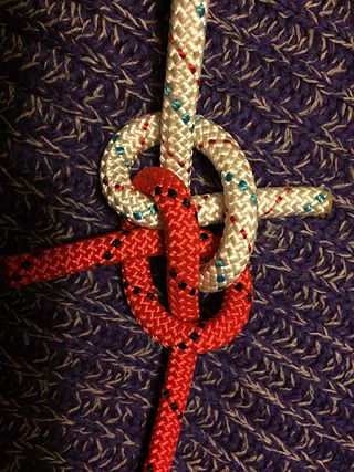
A zeppelin bend is an end-to-end joining knot formed by two symmetrically interlinked overhand knots. It is stable, secure, and highly resistant to jamming. It is also resistant to the effects of slack shaking and cyclic loading.

<span class="mw-page-title-main">Bowden cable</span> Flexible cable used to transmit force

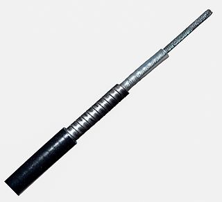
A Bowden cable is a type of flexible cable used to transmit mechanical force or energy by the movement of an inner cable relative to a hollow outer cable housing. The housing is generally of composite construction, consisting of an inner lining, a longitudinally incompressible layer such as a helical winding or a sheaf of steel wire, and a protective outer covering.

<span class="mw-page-title-main">Standing rigging</span> Rigging that supports masts

Standing rigging comprises the fixed lines, wires, or rods, which support each mast or bowsprit on a sailing vessel and reinforce those spars against wind loads transferred from the sails. This term is used in contrast to running rigging, which represents the moveable elements of rigging which adjust the position and shape of the sails.

<span class="mw-page-title-main">Rope</span> Length of braided strands

A rope is a group of yarns, plies, fibres, or strands that are twisted or braided together into a larger and stronger form. Ropes have tensile strength and so can be used for dragging and lifting. Rope is thicker and stronger than similarly constructed cord, string, and twine.

<span class="mw-page-title-main">Tensile structure</span> Structure whose members are only in tension

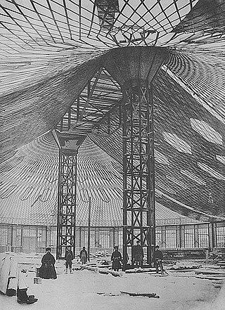
In structural engineering, a tensile structure is a construction of elements carrying only tension and no compression or bending. The term tensile should not be confused with tensegrity, which is a structural form with both tension and compression elements. Tensile structures are the most common type of thin-shell structures.

<span class="mw-page-title-main">Rope splicing</span> Semi-permanent joint between two ropes

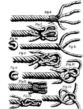
Rope splicing in ropework is the forming of a semi-permanent joint between two ropes or two parts of the same rope by partly untwisting and then interweaving their strands. Splices can be used to form a stopper at the end of a line, to form a loop or an eye in a rope, or for joining two ropes together. Splices are preferred to knotted rope, since while a knot typically reduces the strength by 20–40%, a splice is capable of attaining a rope's full strength. However, splicing usually results in a thickening of the line and, if subsequently removed, leaves a distortion of the rope. Most types of splices are used on three-strand rope, but some can be done on 12-strand or greater single-braided rope, as well as most double braids.

<span class="mw-page-title-main">Guy-wire</span> Tensioned cable designed to add stability to a freestanding structure

A guy-wire, guy-line, guy-rope, down guy, or stay, also called simply a guy, is a tensioned cable designed to add stability to a free-standing structure. They are used commonly for ship masts, radio masts, wind turbines, utility poles, and tents. A thin vertical mast supported by guy wires is called a guyed mast. Structures that support antennas are frequently of a lattice construction and are called "towers". One end of the guy is attached to the structure, and the other is anchored to the ground at some distance from the mast or tower base. The tension in the diagonal guy-wire, combined with the compression and buckling strength of the structure, allows the structure to withstand lateral loads such as wind or the weight of cantilevered structures. They are installed radially, usually at equal angles about the structure, in trios and quads. As the tower leans a bit due to the wind force, the increased guy tension is resolved into a compression force in the tower or mast and a lateral force that resists the wind load. For example, antenna masts are often held up by three guy-wires at 120° angles. Structures with predictable lateral loads, such as electrical utility poles, may require only a single guy-wire to offset the lateral pull of the electrical wires, at a spot where the wires change direction.

Kernmantle rope is rope constructed with its interior core protected by a woven exterior sheath designed to optimize strength, durability, and flexibility. The core fibers provide the tensile strength of the rope, while the sheath protects the core from abrasion during use. This is the only construction of rope that is considered to be life safety rope by most fire and rescue services.

Ultra-high-molecular-weight polyethylene is a subset of the thermoplastic polyethylene. Also known as high-modulus polyethylene (HMPE), it has extremely long chains, with a molecular mass usually between 3.5 and 7.5 million amu. The longer chain serves to transfer load more effectively to the polymer backbone by strengthening intermolecular interactions. This results in a very tough material, with the highest impact strength of any thermoplastic presently made.

<span class="mw-page-title-main">Eye splice</span> Method of creating a loop in the end of a rope

The eye splice is a method of creating a permanent loop in the end of a rope by means of rope splicing.

<span class="mw-page-title-main">Eye bolt</span> Type of bolt

An eye bolt is a bolt with a loop at one end. They are used to firmly attach a securing eye to a structure, so that ropes or cables may then be tied to it.

<span class="mw-page-title-main">Aluminium-conductor steel-reinforced cable</span> Type of overhead power line conductor

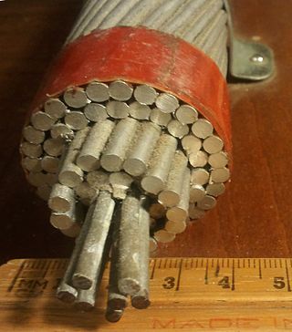
Aluminium conductor steel-reinforced cable (ACSR) is a type of high-capacity, high-strength stranded conductor typically used in overhead power lines. The outer strands are high-purity aluminium, chosen for its good conductivity, low weight, low cost, resistance to corrosion and decent mechanical stress resistance. The centre strand is steel for additional strength to help support the weight of the conductor. Steel is of higher strength than aluminium which allows for increased mechanical tension to be applied on the conductor. Steel also has lower elastic and inelastic deformation due to mechanical loading as well as a lower coefficient of thermal expansion under current loading. These properties allow ACSR to sag significantly less than all-aluminium conductors. As per the International Electrotechnical Commission (IEC) and The CSA Group naming convention, ACSR is designated A1/S1A.

<span class="mw-page-title-main">Bulk-handling crane</span>

A bulk-handlingcrane is one that, instead of a simple hook that can handle a range of slung loads, has an integral grab for lifting bulk cargoes such as coal, mineral ore etc.

<span class="mw-page-title-main">Copper conductor</span> Electrical wire or other conductor made of copper

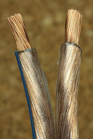
Copper has been used in electrical wiring since the invention of the electromagnet and the telegraph in the 1820s. The invention of the telephone in 1876 created further demand for copper wire as an electrical conductor.

<span class="mw-page-title-main">Wire rope spooling technology</span> Technology to prevent wire rope getting snagged when spooled on a drum

Wire rope spooling technology is the technology to prevent wire rope getting snagged when spooled, especially in multiple layers on a drum.

<span class="mw-page-title-main">Swaged sleeve</span> Mechanically swaged connector

A swaged sleeve is a connector that gets crimped using a hand tool and die (swaged). This type of compressed sleeve is commonly used to make mechanical or conductive connections. These sleeves join or terminate wire rope, aircraft cable, synthetic cable, fibrous rope, or electrical conductor cables.

References

  1. Bergen Cable Technology -- Cable 101 Archived 2014-05-06 at the Wayback Machine
  2. 1 2 "FAQ | Lexco Cable". www.lexcocable.com. Archived from the original on 2017-01-04. Retrieved 2017-01-04.
  3. "Wilhelm Albert". Encyclopædia Britannica . Archived from the original on 9 April 2014. Retrieved 9 April 2014.
  4. Koetsier,Teun; Ceccarelli, Marc (2012). Explorations in the History of Machines and Mechanisms. Springer Publishing. p. 388. ISBN   9789400741324. Archived from the original on 31 March 2017. Retrieved 9 April 2014.
  5. Donald Sayenga. "Modern History of Wire Rope". History of the Atlantic Cable & Submarine Telegraphy (atlantic-cable.com). Archived from the original on 3 February 2014. Retrieved 9 April 2014.
  6. Modern History of Wire Rope - Donald Sayenga Archived 2010-10-27 at the Wayback Machine
  7. Iron: An illustrated weekly journal for iron and steel, Volume 63 by Sholto Percy
  8. 1 2 Modern History of Wire Rope - Donald Sayenga Archived 2010-10-27 at the Wayback Machine
  9. Brenckman, Fred (1918) [1884]. History of Carbon County Pennsylvania: Also Containing a Separate Account of the Several Boroughs and Townships in the County with Biographical Sketches (2nd ed.). Harrisburg, Pennsylvania: James J. Nungesser. p. 627 via archive.org.
  10. Brenckman 1918, Improvements.
  11. The Mechanical Transmission of Power: Endless Rope Drives by Kris De Decker, March 27, 2013 Archived July 7, 2013, at the Wayback Machine
  12. Hunter, Louis C.; Bryant, Lynwood (1991). A History of Industrial Power in the United States, 1730-1930, Vol. 3: The Transmission of Power . Cambridge, Massachusetts, London: MIT Press. ISBN   0-262-08198-9.
  13. "Wire Rope Safety Training". Falck Productions. Archived from the original on 19 January 2015. Retrieved 27 June 2012.
  14. nl:Staalkabel#Slagrichting nl:Staalkabel
  15. bzwxw.com [ permanent dead link ]|title=Steel Wire Ropes - Vocabulary, designation, and classification
  16. Avallone, Eugene; Baumesiter III, Theodore (1978). Marks' Standard Handbook for Mechanical Engineers (Ninth ed.). pp. 10–34. ISBN   0-07-004127-X.
  17. Feyrer, K.: Wire Ropes, Tension, Endurance, Reliability. Springer Berlin, Heidelberg, New York 2007. ISBN   3-540-33821-7
  18. "S9086-UU-STM-010/CH-613R3 NAVAL SHIPS' TECHNICAL MANUAL, CHAPTER 613, WIRE AND FIBER ROPE AND RIGGING" (PDF). Archived (PDF) from the original on 2015-03-05. Retrieved 2021-06-23.
  19. Primer of Towing / George H. Reid - 3rd ed. Fig. 3-5 p30 - Cornell Maritime Press, 2004. ISBN   0-87033-563-4
  20. "S9086-UU-STM-010/CH-613R3 NAVAL SHIPS' TECHNICAL MANUAL, CHAPTER 613, WIRE AND FIBER ROPE AND RIGGING" (PDF). Archived (PDF) from the original on 2015-03-05. Retrieved 2021-06-23.
  21. "Sleeve, Swaging-Wire Rope" (PDF). Retrieved 2021-06-23.[ permanent dead link ]
  22. T R Barnard (1959). "Winding Ropes and Guide Ropes". Mechanical Engineering. Coal Mining Series (2nd ed.). London: Virtue. pp. 374–375.
  23. "Socketfast® Resin Compound". ESCO Corporation. 2015. Archived from the original on 2016-04-21.
  24. "Socket-Lock". 2011. Archived from the original on 2016-04-16.