
A rotary dial is a component of a telephone or a telephone switchboard that implements a signaling technology in telecommunications known as pulse dialing. It is used when initiating a telephone call to transmit the destination telephone number to a telephone exchange.

A relay is an electrically operated switch. It consists of a set of input terminals for a single or multiple control signals, and a set of operating contact terminals. The switch may have any number of contacts in multiple contact forms, such as make contacts, break contacts, or combinations thereof.

In electrical engineering, a switch is an electrical component that can disconnect or connect the conducting path in an electrical circuit, interrupting the electric current or diverting it from one conductor to another. The most common type of switch is an electromechanical device consisting of one or more sets of movable electrical contacts connected to external circuits. When a pair of contacts is touching current can pass between them, while when the contacts are separated no current can flow.

Pulse dialing is a signaling technology in telecommunications in which a direct current local loop circuit is interrupted according to a defined coding system for each signal transmitted, usually a digit. This lends the method the often used name loop disconnect dialing. In the most common variant of pulse dialing, decadic dialing, each of the ten Arabic numerals are encoded in a sequence of up to ten pulses. The most common version decodes the digits 1 through 9, as one to nine pulses, respectively, and the digit 0 as ten pulses. Historically, the most common device to produce such pulse trains is the rotary dial of the telephone, lending the technology another name, rotary dialing.

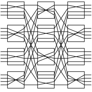
In electronics and telecommunications, a crossbar switch is a collection of switches arranged in a matrix configuration. A crossbar switch has multiple input and output lines that form a crossed pattern of interconnecting lines between which a connection may be established by closing a switch located at each intersection, the elements of the matrix. Originally, a crossbar switch consisted literally of crossing metal bars that provided the input and output paths. Later implementations achieved the same switching topology in solid-state electronics. The crossbar switch is one of the principal telephone exchange architectures, together with a rotary switch, memory switch, and a crossover switch.
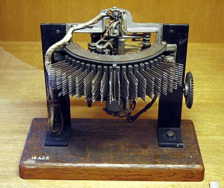
The Strowger switch is the first commercially successful electromechanical stepping switch telephone exchange system. It was developed by the Strowger Automatic Telephone Exchange Company founded in 1891 by Almon Brown Strowger. Because of its operational characteristics, it is also known as a step-by-step (SXS) switch.
A nonblocking minimal spanning switch is a device that can connect N inputs to N outputs in any combination. The most familiar use of switches of this type is in a telephone exchange. The term "non-blocking" means that if it is not defective, it can always make the connection. The term "minimal" means that it has the fewest possible components, and therefore the minimal expense.

The reed switch is an electromechanical switch operated by an applied magnetic field. It was invented in 1922 by professor Valentin Kovalenkov at the Petrograd Electrotechnical University, and later evolved at Bell Telephone Laboratories in 1936 by Walter B. Ellwood into the reed relay. In its simplest and most common form, it consists of a pair of ferromagnetic flexible metal contacts in a hermetically sealed glass envelope. The contacts are usually normally open, closing when a magnetic field is present, or they may be normally closed and open when a magnetic field is applied. The switch may be actuated by an electromagnetic coil, making a reed relay, or by bringing a permanent magnet near it. When the magnetic field is removed, the contacts in the reed switch return to their original position. The "reed" is the metal part inside the reed switch envelope that is relatively thin and wide to make it flexible, resembling the reed of a musical instrument. The term "reed" may also include the external wire lead as well as the internal part.
In electrical engineering, a stepping switch or stepping relay, also known as a uniselector, is an electromechanical device that switches an input signal path to one of several possible output paths, directed by a train of electrical pulses.
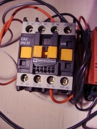
A contactor is an electrically controlled switch used for switching an electrical power circuit. A contactor is typically controlled by a circuit which has a much lower power level than the switched circuit, such as a 24-volt coil electromagnet controlling a 230-volt motor switch.

A marker is a type of special purpose control system that was used in electromechanical telephone central office switches. Switches employing markers belong to a class of switches known as "common control", as the purpose of a marker is to control the closure of contacts in the switching fabric that connect a circuit between the calling party and the called party. This is in contrast to "direct control" switches, where the switching elements were controlled directly by the customer's dial, such as the Step by Step switch. The term marker came from its use to mark a path of links through the switching fabric. A marker's comprehensive view of the switching fabric allowed it to find and assemble a path from one terminal to another, if the links were available, unlike the earlier graded progressive systems in which a path might not be found.
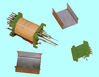
A reed relay is a type of relay that uses an electromagnet to control one or more reed switches. The contacts are of magnetic material and the electromagnet acts directly on them without requiring an armature to move them. Sealed in a long, narrow glass tube, the contacts are protected from corrosion. The glass envelope may contain multiple reed switches or multiple reed switches can be inserted into a single bobbin and actuate simultaneously. Reed switches have been manufactured since the 1930s.
The Number Five Crossbar Switching System is a telephone switch for telephone exchanges designed by Bell Labs and manufactured by Western Electric starting in 1947. It was used in the Bell System principally as a Class 5 telephone switch in the public switched telephone network (PSTN) until the early 1990s, when it was replaced with electronic switching systems. Variants were used as combined Class 4 and Class 5 systems in rural areas, and as a TWX switch.
The Number One Crossbar Switching System (1XB), was the primary technology for urban telephone exchanges served by the Bell System in the mid-20th century. Its switch fabric used the electromechanical crossbar switch to implement the topology of the panel switching system of the 1920s. The first No. 1 Crossbar was installed in the PResident-2 central office at Troy Avenue in Brooklyn, New York which became operational in February 1938.
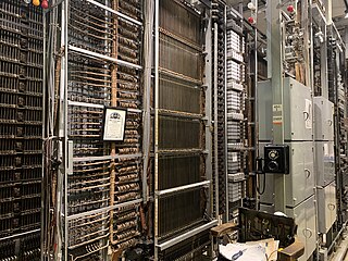
The Number One Electronic Switching System (1ESS) was the first large-scale stored program control (SPC) telephone exchange or electronic switching system in the Bell System. It was manufactured by Western Electric and first placed into service in Succasunna, New Jersey, in May 1965. The switching fabric was composed of a reed relay matrix controlled by wire spring relays which in turn were controlled by a central processing unit (CPU).
TXE, was a family of telephone exchanges developed by the British General Post Office (GPO), designed to replace the ageing Strowger switches.
Relay logic is a method of implementing combinational logic in electrical control circuits by using several electrical relays wired in a particular configuration.

A magnetic starter is an electromagnetically operated switch which provides a safe method for starting an electric motor with a large load. Magnetic starters also provide under-voltage and overload protection and an automatic cutoff in the event of a power failure.

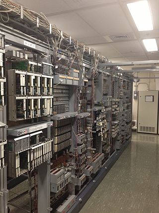
A telephone exchange, also known as a telephone switch or central office, is a crucial component in the public switched telephone network (PSTN) or large enterprise telecommunications systems. It facilitates the interconnection of telephone subscriber lines or digital system virtual circuits, enabling telephone calls between subscribers.
The Panel Machine Switching System is a type of automatic telephone exchange for urban service that was used in the Bell System in the United States for seven decades. The first semi-mechanical types of this design were installed in 1915 in Newark, New Jersey, and the last were retired in the same city in 1983.
