
The Intel 8080 ("eighty-eighty") is the second 8-bit microprocessor designed and manufactured by Intel. It first appeared in April 1974 and is an extended and enhanced variant of the earlier 8008 design, although without binary compatibility. The initial specified clock rate or frequency limit was 2 MHz, with common instructions using 4, 5, 7, 10, or 11 cycles. As a result, the processor is able to execute several hundred thousand instructions per second. Two faster variants, the 8080A-1 and 8080A-2, became available later with clock frequency limits of 3.125 MHz and 2.63 MHz respectively. The 8080 needs two support chips to function in most applications: the i8224 clock generator/driver and the i8228 bus controller. It is implemented in N-type metal-oxide-semiconductor logic (NMOS) using non-saturated enhancement mode transistors as loads thus demanding a +12 V and a −5 V voltage in addition to the main transistor–transistor logic (TTL) compatible +5 V.
A microcontroller is a small computer on a single VLSI integrated circuit (IC) chip. A microcontroller contains one or more CPUs along with memory and programmable input/output peripherals. Program memory in the form of ferroelectric RAM, NOR flash or OTP ROM is also often included on chip, as well as a small amount of RAM. Microcontrollers are designed for embedded applications, in contrast to the microprocessors used in personal computers or other general purpose applications consisting of various discrete chips.

In electronics, a multiplexer, also known as a data selector, is a device that selects between several analog or digital input signals and forwards the selected input to a single output line. The selection is directed by a separate set of digital inputs known as select lines. A multiplexer of inputs has select lines, which are used to select which input line to send to the output.

Digital electronics is a field of electronics involving the study of digital signals and the engineering of devices that use or produce them. This is in contrast to analog electronics and analog signals.
Transistor–transistor logic (TTL) is a logic family built from bipolar junction transistors. Its name signifies that transistors perform both the logic function and the amplifying function, as opposed to earlier resistor–transistor logic (RTL) and diode–transistor logic (DTL).

A programmable logic device (PLD) is an electronic component used to build reconfigurable digital circuits. Unlike digital logic constructed using discrete logic gates with fixed functions, a PLD has an undefined function at the time of manufacture. Before the PLD can be used in a circuit it must be programmed to implement the desired function. Compared to fixed logic devices, programmable logic devices simplify the design of complex logic and may offer superior performance. Unlike for microprocessors, programming a PLD changes the connections made between the gates in the device.

Dynamic random-access memory is a type of random-access semiconductor memory that stores each bit of data in a memory cell, usually consisting of a tiny capacitor and a transistor, both typically based on metal-oxide-semiconductor (MOS) technology. While most DRAM memory cell designs use a capacitor and transistor, some only use two transistors. In the designs where a capacitor is used, the capacitor can either be charged or discharged; these two states are taken to represent the two values of a bit, conventionally called 0 and 1. The electric charge on the capacitors gradually leaks away; without intervention the data on the capacitor would soon be lost. To prevent this, DRAM requires an external memory refresh circuit which periodically rewrites the data in the capacitors, restoring them to their original charge. This refresh process is the defining characteristic of dynamic random-access memory, in contrast to static random-access memory (SRAM) which does not require data to be refreshed. Unlike flash memory, DRAM is volatile memory, since it loses its data quickly when power is removed. However, DRAM does exhibit limited data remanence.

In digital logic, an inverter or NOT gate is a logic gate which implements logical negation. It outputs a bit opposite of the bit that is put into it. The bits are typically implemented as two differing voltage levels.

The Intel 4004 is a 4-bit central processing unit (CPU) released by Intel Corporation in 1971. Sold for US$60, it was the first commercially produced microprocessor, and the first in a long line of Intel CPUs.
In digital electronics, a binary decoder is a combinational logic circuit that converts binary information from the n coded inputs to a maximum of 2n unique outputs. They are used in a wide variety of applications, including instruction decoding, data multiplexing and data demultiplexing, seven segment displays, and as address decoders for memory and port-mapped I/O.
Memory-mapped I/O (MMIO) and port-mapped I/O (PMIO) are two complementary methods of performing input/output (I/O) between the central processing unit (CPU) and peripheral devices in a computer. An alternative approach is using dedicated I/O processors, commonly known as channels on mainframe computers, which execute their own instructions.
The Serial Peripheral Interface (SPI) is a synchronous serial communication interface specification used for short-distance communication, primarily in embedded systems. The interface was developed by Motorola in the mid-1980s and has become a de facto standard. Typical applications include Secure Digital cards and liquid crystal displays.

1-Wire is a device communications bus system designed by Dallas Semiconductor Corp. that provides low-speed data, signaling, and power over a single conductor.
JTAG is an industry standard for verifying designs and testing printed circuit boards after manufacture.
In digital electronics, especially computing, hardware registers are circuits typically composed of flip flops, often with many characteristics similar to memory, such as:
In digital electronics, a tri-state or three-state buffer is a type of digital buffer that has three stable states: a high output state, a low output state, and a high-impedance state. In the high-impedance state, the output of the buffer is disconnected from the output bus, allowing other devices to drive the bus without interference from the tri-state buffer. This can be useful in situations where multiple devices are connected to the same bus and need to take turns accessing it.
The memory controller is a digital circuit that manages the flow of data going to and from the computer's main memory. A memory controller can be a separate chip or integrated into another chip, such as being placed on the same die or as an integral part of a microprocessor; in the latter case, it is usually called an integrated memory controller (IMC). A memory controller is sometimes also called a memory chip controller (MCC) or a memory controller unit (MCU).
In digital circuits, a logic level is one of a finite number of states that a digital signal can inhabit. Logic levels are usually represented by the voltage difference between the signal and ground, although other standards exist. The range of voltage levels that represent each state depends on the logic family being used. A logic-level shifter can be used to allow compatibility between different circuits.

A DTV receiver is a set-top box that permits the reception of digital television. Its components are very similar to a desktop PC. The DTV receiver is a vital link in the chain of television system. The goal of a broadcasting system is to concentrate the hardware requirements at the source to simplify the receivers and makes it as inexpensive as possible.
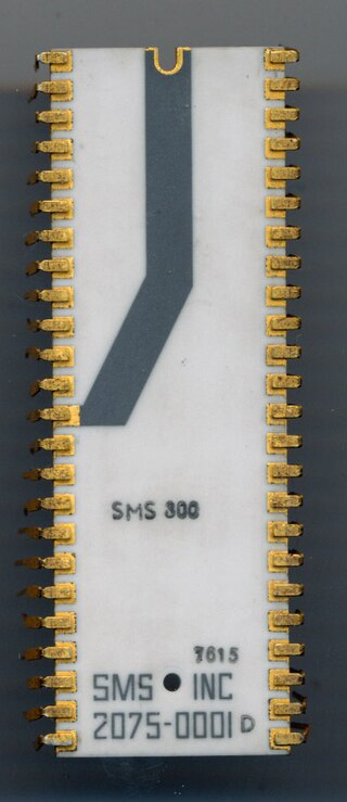
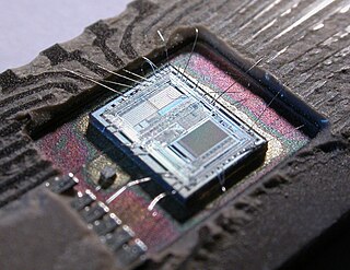
The 8X300 is a microprocessor produced and marketed by Signetics starting 1976 as a second source for the SMS 300 by Scientific Micro Systems, Inc. Although SMS developed the SMS 300, Signetics was the sole manufacturer of this product line. In 1978 Signetics purchased the rights to the SMS 300 series and renamed it 8X300.
