Related Research Articles

In electronics, an analog-to-digital converter is a system that converts an analog signal, such as a sound picked up by a microphone or light entering a digital camera, into a digital signal. An ADC may also provide an isolated measurement such as an electronic device that converts an analog input voltage or current to a digital number representing the magnitude of the voltage or current. Typically the digital output is a two's complement binary number that is proportional to the input, but there are other possibilities.

Pulse-width modulation (PWM), or pulse-duration modulation (PDM), is a method of reducing the average power delivered by an electrical signal, by effectively chopping it up into discrete parts. The average value of voltage fed to the load is controlled by turning the switch between supply and load on and off at a fast rate. The longer the switch is on compared to the off periods, the higher the total power supplied to the load. Along with maximum power point tracking (MPPT), it is one of the primary methods of reducing the output of solar panels to that which can be utilized by a battery. PWM is particularly suited for running inertial loads such as motors, which are not as easily affected by this discrete switching, because their inertia causes them to react slowly. The PWM switching frequency has to be high enough not to affect the load, which is to say that the resultant waveform perceived by the load must be as smooth as possible.

A power supply is an electrical device that supplies electric power to an electrical load. The main purpose of a power supply is to convert electric current from a source to the correct voltage, current, and frequency to power the load. As a result, power supplies are sometimes referred to as electric power converters. Some power supplies are separate standalone pieces of equipment, while others are built into the load appliances that they power. Examples of the latter include power supplies found in desktop computers and consumer electronics devices. Other functions that power supplies may perform include limiting the current drawn by the load to safe levels, shutting off the current in the event of an electrical fault, power conditioning to prevent electronic noise or voltage surges on the input from reaching the load, power-factor correction, and storing energy so it can continue to power the load in the event of a temporary interruption in the source power.

A power inverter, inverter or invertor is a power electronic device or circuitry that changes direct current (DC) to alternating current (AC). The resulting AC frequency obtained depends on the particular device employed. Inverters do the opposite of "converters" which were originally large electromechanical devices converting AC to DC.
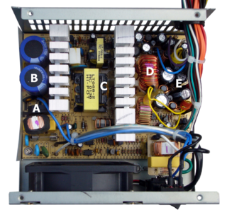
A switched-mode power supply is an electronic power supply that incorporates a switching regulator to convert electrical power efficiently.

In electronics, a sample and hold circuit is an analog device that samples the voltage of a continuously varying analog signal and holds its value at a constant level for a specified minimum period of time. Sample and hold circuits and related peak detectors are the elementary analog memory devices. They are typically used in analog-to-digital converters to eliminate variations in input signal that can corrupt the conversion process. They are also used in electronic music, for instance to impart a random quality to successively-played notes.
A DC-to-DC converter is an electronic circuit or electromechanical device that converts a source of direct current (DC) from one voltage level to another. It is a type of electric power converter. Power levels range from very low to very high.

A voltage regulator is a system designed to automatically maintain a constant voltage. A voltage regulator may use a simple feed-forward design or may include negative feedback. It may use an electromechanical mechanism, or electronic components. Depending on the design, it may be used to regulate one or more AC or DC voltages.

Power electronics is the application of electronics to the control and conversion of electric power.
A voltage doubler is an electronic circuit which charges capacitors from the input voltage and switches these charges in such a way that, in the ideal case, exactly twice the voltage is produced at the output as at its input.
Delta-sigma modulation is a method for encoding analog signals into digital signals as found in an analog-to-digital converter (ADC). It is also used to convert high bit-count, low-frequency digital signals into lower bit-count, higher-frequency digital signals as part of the process to convert digital signals into analog as part of a digital-to-analog converter (DAC).

A class-D amplifier or switching amplifier is an electronic amplifier in which the amplifying devices operate as electronic switches, and not as linear gain devices as in other amplifiers. They operate by rapidly switching back and forth between the supply rails, being fed by a modulator using pulse width, pulse density, or related techniques to encode the audio input into a pulse train. The audio escapes through a simple low-pass filter into the loudspeaker. The high-frequency pulses are blocked. Since the pairs of output transistors are never conducting at the same time, there is no other path for current flow apart from the low-pass filter/loudspeaker. For this reason, efficiency can exceed 90%.

A buck converter is a DC-to-DC power converter which steps down voltage from its input (supply) to its output (load). It is a class of switched-mode power supply (SMPS) typically containing at least two semiconductors and at least one energy storage element, a capacitor, inductor, or the two in combination. To reduce voltage ripple, filters made of capacitors are normally added to such a converter's output and input. It is called a buck converter because the voltage across the inductor “bucks” or opposes the supply voltage.
A H-bridge is an electronic circuit that switches the polarity of a voltage applied to a load. These circuits are often used in robotics and other applications to allow DC motors to run forwards or backwards. The name is derived from its common schematic diagram representation, with four switching elements configured as the branches of a letter "H" and the load connected as the cross-bar.
Pulse-frequency modulation (PFM) is a modulation method for representing an analog signal using only two levels. It is analogous to pulse-width modulation (PWM), in which the magnitude of an analog signal is encoded in the duty cycle of a square wave. Unlike PWM, in which the width of square pulses is varied at a constant frequency, PFM fixes the width of square pulses while varying the frequency. In other words, the frequency of the pulse train is varied in accordance with the instantaneous amplitude of the modulating signal at sampling intervals. The amplitude and width of the pulses are kept constant.
The Sparse Matrix Converter is an AC/AC converter which offers a reduced number of components, a low-complexity modulation scheme, and low realization effort. Invented in 2001 by Prof Johann W. Kolar , sparse matrix converters avoid the multi step commutation procedure of the conventional matrix converter, improving system reliability in industrial operations. Its principal application is in highly compact integrated AC drives.

A digital signal is a signal that represents data as a sequence of discrete values; at any given time it can only take on, at most, one of a finite number of values. This contrasts with an analog signal, which represents continuous values; at any given time it represents a real number within a continuous range of values.
The following outline is provided as an overview of and topical guide to electronics:
This glossary of electrical and electronics engineering is a list of definitions of terms and concepts related specifically to electrical engineering and electronics engineering. For terms related to engineering in general, see Glossary of engineering.
This glossary of power electronics is a list of definitions of terms and concepts related to power electronics in general and power electronic capacitors in particular. For more definitions in electric engineering, see Glossary of electrical and electronics engineering. For terms related to engineering in general, see Glossary of engineering.
References
- 1 2 3 US 3659184,Schwarz, Francisc C.,"Analog signal to discrete time interval converter (ASDTIC)",published 1972-04-25, assigned to NASA
- ↑ Schoenfeld, A. D.; Yu, Y. (February 1973). "ASDTIC control and standardized interface circuits applied to buck, parallel and buck-boost dc to dc power converters". NASA. NASA CR-121106.
- 1 2 3 4 5 Schoenfeld, A. D.; Yu, Y. (August 1, 1973). "The application of the analog signal to discrete time interval converter to the signal conditioner power supplies" (PDF). NASA. NASA CR-120906.
- ↑ Research contract NAS12-2017, December 1969 – October 1970, TRW for NASA Lewis Research Center