Anechoic chamber

Last updated

360-degree image of an acoustic anechoic chamber 360 anechoic chamber salford university uk.jpg
360-degree image of an acoustic anechoic chamber
360-degree image of an electromagnetic anechoic chamber 360 image of an electromagnetic anechoic chamber.jpg
360-degree image of an electromagnetic anechoic chamber

An anechoic chamber (an-echoic meaning "non-reflective" or "without echoes") is a room designed to stop reflections or echoes of either sound or electromagnetic waves. They are also often isolated from energy entering from their surroundings. This combination means that a person or detector exclusively hears direct sounds (no reflected sounds), in effect simulating being outside in a free field.

Contents

Anechoic chambers, a term coined by American acoustics expert Leo Beranek, were initially exclusively used to refer to acoustic anechoic chambers. Recently, the term has been extended to other radio frequency (RF) and sonar anechoic chambers, which eliminate reflection and external noise caused by electromagnetic waves.

Anechoic chambers range from small compartments the size of household microwave ovens to ones as large as aircraft hangars. The size of the chamber depends on the size of the objects and frequency ranges being tested.

Acoustic anechoic chambers

Minimization of the reflection of sound waves by an anechoic chamber's walls Anechoic chamber dissipation.jpg
Minimization of the reflection of sound waves by an anechoic chamber's walls
Testing headphones in the Consumer Reports anechoic chamber Consumer Reports - product testing - headphones in anechoic chamber.tif
Testing headphones in the Consumer Reports anechoic chamber

The requirement for what was subsequently called an anechoic chamber originated to allow testing of loudspeakers that generated such intense sound levels that they could not be tested outdoors in inhabited areas. [1]

Anechoic chambers are commonly used in acoustics to conduct experiments in nominally "free field" conditions, free field meaning that there are no reflected signals. All sound energy will be traveling away from the source with almost none reflected back. Common anechoic chamber experiments include measuring the transfer function of a loudspeaker or the directivity of noise radiation from industrial machinery. In general, the interior of an anechoic chamber can be very quiet, with typical noise levels in the 10–20 dBA range. In 2005, the best anechoic chamber measured at −9.4 dBA. [2] In 2015, an anechoic chamber on the campus of Microsoft broke the world record with a measurement of −20.6 dBA. [3] The human ear can typically detect sounds above 0 dBA, so a human in such a chamber would perceive the surroundings as devoid of sound. Anecdotally, some people may not like such silence and can become disoriented. [2]

The mechanism by which anechoic chambers minimize the reflection of sound waves impinging onto their walls is as follows: In the included figure, an incident sound wave I is about to impinge onto a wall of an anechoic chamber. This wall is composed of a series of wedges W with height H. After the impingement, the incident wave I is reflected as a series of waves R which in turn "bounce up-and-down" in the gap of air A (bounded by dotted lines) between the wedges W. Such bouncing may produce (at least temporarily) a standing wave pattern in A. During this process, the acoustic energy of the waves R gets dissipated via the air's molecular viscosity, in particular near the corner C. [4] In addition, with the use of foam materials to fabricate the wedges, another dissipation mechanism happens during the wave/wall interactions. [5] As a result, the component of the reflected waves R along the direction of I that escapes the gaps A (and goes back to the source of sound), denoted R', is notably reduced. Even though this explanation is two-dimensional, it is representative and applicable to the actual three-dimensional wedge structures used in anechoic chambers. [6]

Semi-anechoic and hemi-anechoic chambers

Full anechoic chambers aim to absorb energy in all directions. To do this, all surfaces, including the floor, need to be covered in correctly shaped wedges. A mesh grille is usually installed above the floor to provide a surface to walk on and place equipment. This mesh floor is typically placed at the same floor level as the rest of the building, meaning the chamber itself extends below floor level. This mesh floor is damped and floating on absorbent buffers to isolate it from outside vibration or electromagnetic signals.

In contrast, semi-anechoic or hemi-anechoic chambers have a solid floor that acts as a work surface for supporting heavy items, such as cars, washing machines, or industrial machinery, which could not be supported by the mesh grille in a full anechoic chamber. Recording studios are often semi-anechoic.

The distinction between "semi-anechoic" and "hemi-anechoic" is unclear. In some uses they are synonyms, or only one term is used. [7] Other uses distinguish one as having an ideally reflective floor (creating free-field conditions with a single reflective surface) and the other as simply having a flat untreated floor. [8] [9] Still other uses distinguish them by size and performance, with one being likely an existing room retrofitted with acoustic treatment, and the other a purpose-built room which is likely larger and has better anechoic performance. [10]

Radio-frequency anechoic chambers

An RF anechoic chamber Radio-frequency-anechoic-chamber-HDR-0a.jpg
An RF anechoic chamber
A large drive-in EMC RF anechoic test chamber. Note the orange caution cones for size reference. Large Drive-In EMC Test Chamber.png
A large drive-in EMC RF anechoic test chamber. Note the orange caution cones for size reference.
An F-16 Fighting Falcon in the anechoic test chamber at Eglin Air Force Base 40th Flight Test Squadron F-16 Fighting Falcon sits in the anechoic chamber.jpg
An F-16 Fighting Falcon in the anechoic test chamber at Eglin Air Force Base

The internal appearance of the radio frequency (RF) anechoic chamber is sometimes similar to that of an acoustic anechoic chamber; however, the interior surfaces of the RF anechoic chamber are covered with radiation absorbent material (RAM) instead of acoustically absorbent material. Uses for RF anechoic chambers include testing antennas and radars, and they are typically used to house the antennas for performing measurements of antenna radiation patterns and electromagnetic interference.

Performance expectations (gain, efficiency, pattern characteristics, etc.) constitute primary challenges in designing stand alone or embedded antennas. Designs are becoming ever more complex with a single device incorporating multiple technologies such as cellular, WiFi, Bluetooth, LTE, MIMO, RFID and GPS.

Radiation-absorbent material

RAM is designed and shaped to absorb incident RF radiation (also known as non-ionising radiation) as effectively as possible, from as many incident directions as possible. The more effective the RAM, the lower the resulting level of reflected RF radiation. Many measurements in electromagnetic compatibility (EMC) and antenna radiation patterns require that spurious signals arising from the test setup, including reflections, are negligible to avoid the risk of causing measurement errors and ambiguities.

Effectiveness over frequency

Close-up of a pyramidal RAM Anechoic chamber wall.JPG
Close-up of a pyramidal RAM

Waves of higher frequencies have shorter wavelengths and are higher in energy, while waves of lower frequencies have longer wavelengths and are lower in energy, according to the relationship where lambda represents wavelength, v is phase velocity of wave, and is frequency. To shield for a specific wavelength, the cone must be of appropriate size to absorb that wavelength. The performance quality of an RF anechoic chamber is determined by its lowest test frequency of operation, at which measured reflections from the internal surfaces will be the most significant compared to higher frequencies. Pyramidal RAM is at its most absorptive when the incident wave is at normal incidence to the internal chamber surface and the pyramid height is approximately equal to , where is the free space wavelength. Accordingly, increasing the pyramid height of the RAM for the same (square) base size improves the effectiveness of the chamber at low frequencies but results in increased cost and a reduced unobstructed working volume that is available inside a chamber of defined size.

Installation into a screened room

An RF anechoic chamber is usually built into a screened room, designed using the Faraday cage principle. This is because most of the RF tests that require an anechoic chamber to minimize reflections from the inner surfaces also require the properties of a screened room to attenuate unwanted signals penetrating inwards and causing interference to the equipment under test and prevent leakage from tests penetrating outside. Pyramidal RAM absorber can also be built by additive manufacturing, allowing to explore internal patterns, in order to improve absorptive effects. [11]

Chamber size and commissioning

At lower radiated frequencies, far-field measurement can require a large and expensive chamber. Sometimes, for example for radar cross-section measurements, it is possible to scale down the object under test and reduce the chamber size, provided that the wavelength of the test frequency is scaled down in direct proportion by testing at a higher frequency.[ citation needed ]

RF anechoic chambers are normally designed to meet the electrical requirements of one or more accredited standards. For example, the aircraft industry may test equipment for aircraft according to company specifications or military specifications such as MIL-STD 461E. Once built, acceptance tests are performed during commissioning to verify that the standard(s) are in fact met. Provided they are, a certificate will be issued to that effect. The chamber will need to be periodically retested.

Operational use

Test and supporting equipment configurations to be used within anechoic chambers must expose as few metallic (conductive) surfaces as possible, as these risk causing unwanted reflections. Often this is achieved by using non-conductive plastic or wooden structures for supporting the equipment under test. Where metallic surfaces are unavoidable, they may be covered with pieces of RAM after setting up to minimize such reflection as far as possible.

A careful assessment may be required as to whether the test equipment (as opposed to the equipment under test) should be placed inside or outside the chamber. Typically most of it is located in a separate screened room attached to the main test chamber, in order to shield it from both external interference and from the radiation within the chamber. Mains power and test signal cabling into the test chamber require high quality filtering.

Fiber optic cables are sometimes used for the signal cabling, as they are immune to ordinary RFI and also cause little reflection inside the chamber.

Health and safety risks associated with RF anechoic chamber

The following health and safety risks are associated with RF anechoic chambers:

Personnel are not normally permitted inside the chamber during a measurement as this not only can cause unwanted reflections from the human body but may also be a radiation hazard to the personnel concerned if tests are being performed at high RF powers. Such risks are from RF or non-ionizing radiation and not from the higher energy ionizing radiation.

As RAM is highly absorptive of RF radiation, incident radiation will generate heat within the RAM. If this cannot be dissipated adequately there is a risk that hot spots may develop and the RAM temperature may rise to the point of combustion. This can be a risk if a transmitting antenna inadvertently gets too close to the RAM. Even for quite modest transmitting power levels, high gain antennas can concentrate the power sufficiently to cause high power flux near their apertures. Although recently manufactured RAM is normally treated with a fire retardant to reduce such risks, they are difficult to eliminate. Safety regulations normally require the installation of a gaseous fire suppression system including smoke detectors.

See also

Related Research Articles

<span class="mw-page-title-main">Microwave</span> Electromagnetic radiation with wavelengths from 1 m to 1 mm

Microwave is a form of electromagnetic radiation with wavelengths ranging from about 30 centimeters to one millimeter corresponding to frequencies between 1 GHz and 300 GHz respectively. Different sources define different frequency ranges as microwaves; the above broad definition includes UHF, SHF and EHF bands. A more common definition in radio-frequency engineering is the range between 1 and 100 GHz. In all cases, microwaves include the entire SHF band at minimum. Frequencies in the microwave range are often referred to by their IEEE radar band designations: S, C, X, Ku, K, or Ka band, or by similar NATO or EU designations.

<span class="mw-page-title-main">Electromagnetic compatibility</span> Electrical engineering concept

Electromagnetic compatibility (EMC) is the ability of electrical equipment and systems to function acceptably in their electromagnetic environment, by limiting the unintentional generation, propagation and reception of electromagnetic energy which may cause unwanted effects such as electromagnetic interference (EMI) or even physical damage to operational equipment. The goal of EMC is the correct operation of different equipment in a common electromagnetic environment. It is also the name given to the associated branch of electrical engineering.

<span class="mw-page-title-main">Waveguide</span> Structure that guides waves efficiently

A waveguide is a structure that guides waves by restricting the transmission of energy to one direction. Common types of waveguides include acoustic waveguides which direct sound, optical waveguides which direct light, and radio-frequency waveguides which direct electromagnetic waves other than light like radio waves.

<span class="mw-page-title-main">Radio wave</span> Type of electromagnetic radiation

Radio waves are a type of electromagnetic radiation with the longest wavelengths in the electromagnetic spectrum, typically with frequencies of 300 gigahertz (GHz) and below. At 300 GHz, the corresponding wavelength is 1mm, which is shorter than the diameter of a grain of rice. At 30 Hz the corresponding wavelength is ~10,000 kilometers, which is longer than the radius of the Earth. Wavelength of a radio wave is inversely proportional to its frequency, because its velocity is constant. Like all electromagnetic waves, radio waves in a vacuum travel at the speed of light, and in the Earth's atmosphere at a slightly slower speed. Radio waves are generated by charged particles undergoing acceleration, such as time-varying electric currents. Naturally occurring radio waves are emitted by lightning and astronomical objects, and are part of the blackbody radiation emitted by all warm objects.

<span class="mw-page-title-main">Faraday cage</span> Enclosure of conductive mesh used to block electric fields

A Faraday cage or Faraday shield is an enclosure used to block electromagnetic fields. A Faraday shield may be formed by a continuous covering of conductive material, or in the case of a Faraday cage, by a mesh of such materials. Faraday cages are named after scientist Michael Faraday, who first constructed one in 1836.

<span class="mw-page-title-main">Antenna (radio)</span> Electrical device

In radio engineering, an antenna or aerial is the interface between radio waves propagating through space and electric currents moving in metal conductors, used with a transmitter or receiver. In transmission, a radio transmitter supplies an electric current to the antenna's terminals, and the antenna radiates the energy from the current as electromagnetic waves. In reception, an antenna intercepts some of the power of a radio wave in order to produce an electric current at its terminals, that is applied to a receiver to be amplified. Antennas are essential components of all radio equipment.

Room acoustics is a subfield of acoustics dealing with the behaviour of sound in enclosed or partially-enclosed spaces. The architectural details of a room influences the behaviour of sound waves within it, with the effects varying by frequency. Acoustic reflection, diffraction, and diffusion can combine to create audible phenomena such as room modes and standing waves at specific frequencies and locations, echos, and unique reverberation patterns.

<span class="mw-page-title-main">Reflection (physics)</span> "Bouncing back" of waves at an interface

Reflection is the change in direction of a wavefront at an interface between two different media so that the wavefront returns into the medium from which it originated. Common examples include the reflection of light, sound and water waves. The law of reflection says that for specular reflection the angle at which the wave is incident on the surface equals the angle at which it is reflected.

<span class="mw-page-title-main">Resonator</span> Device or system that exhibits resonance

A resonator is a device or system that exhibits resonance or resonant behavior. That is, it naturally oscillates with greater amplitude at some frequencies, called resonant frequencies, than at other frequencies. The oscillations in a resonator can be either electromagnetic or mechanical. Resonators are used to either generate waves of specific frequencies or to select specific frequencies from a signal. Musical instruments use acoustic resonators that produce sound waves of specific tones. Another example is quartz crystals used in electronic devices such as radio transmitters and quartz watches to produce oscillations of very precise frequency.

<span class="mw-page-title-main">Radar cross section</span> Strength of an objects radar echo

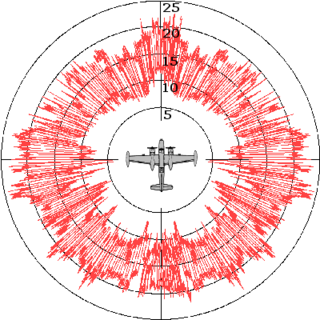
Radar cross-section (RCS), denoted σ, also called radar signature, is a measure of how detectable an object is by radar. A larger RCS indicates that an object is more easily detected.

A reverberation room or reverberation chamber is a room designed to create reverberation, a diffuse or random incidence sound field. Reverberation chambers tend to be large rooms and have very hard exposed surfaces. The change of impedance these surfaces present to incident sound is so large that virtually all of the acoustic energy that hits a surface is reflected back into the room. Arranging the room surfaces to be non-parallel helps inhibit the formation of standing waves - additional acoustic diffusers are often used to create more reflecting surfaces and further encourage even distribution of any particular sound field.

<span class="mw-page-title-main">Absorption (acoustics)</span> When an object takes in energy from sound waves instead of reflecting them

In acoustics, absorption refers to the process by which a material, structure, or object takes in sound energy when sound waves are encountered, as opposed to reflecting the energy. Part of the absorbed energy is transformed into heat and part is transmitted through the absorbing body. The energy transformed into heat is said to have been 'lost'.

Antenna measurement techniques refers to the testing of antennas to ensure that the antenna meets specifications or simply to characterize it. Typical parameters of antennas are gain, bandwidth, radiation pattern, beamwidth, polarization, and impedance.

<span class="mw-page-title-main">Acoustic foam</span> Open called foam used for soundproofing

Acoustic foam is an open celled foam used for acoustic treatment. It attenuates airbone sound waves, reducing their amplitude, for the purposes of noise reduction or noise control. The energy is dissipated as heat. Acoustic foam can be made in several different colors, sizes and thickness.

<span class="mw-page-title-main">Radiation-absorbent material</span> RAM Technology

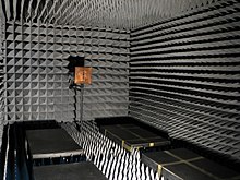
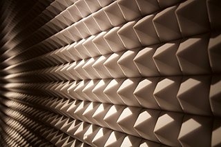
In materials science, radiation-absorbent material (RAM) is a material which has been specially designed and shaped to absorb incident RF radiation, as effectively as possible, from as many incident directions as possible. The more effective the RAM, the lower the resulting level of reflected RF radiation. Many measurements in electromagnetic compatibility (EMC) and antenna radiation patterns require that spurious signals arising from the test setup, including reflections, are negligible to avoid the risk of causing measurement errors and ambiguities.

Room modes are the collection of resonances that exist in a room when the room is excited by an acoustic source such as a loudspeaker. Most rooms have their fundamental resonances in the 20 Hz to 200 Hz region, each frequency being related to one or more of the room's dimensions or a divisor thereof. These resonances affect the low-frequency low-mid-frequency response of a sound system in the room and are one of the biggest obstacles to accurate sound reproduction.

<span class="mw-page-title-main">Loudspeaker measurement</span> Quantifying the behaviour of loudspeakers

Loudspeaker measurement is the practice of determining the behaviour of loudspeakers by measuring various aspects of performance. This measurement is especially important because loudspeakers, being transducers, have a higher level of distortion than other audio system components used in playback or sound reinforcement.

A TEM or transverse electromagnetic cell is a type of test chamber used to perform electromagnetic compatibility (EMC) or electromagnetic interference (EMI) testing. It allows for the creation of far field electromagnetic fields in a small enclosed setting, or the detection of electromagnetic fields radiated within the chamber.

An acoustic duct or plane wave tube is a test facility used in acoustics. Anechoic chambers are typically subject to a low frequency limit, governed by the length of the sound absorbing wedges employed to prevent reflections within the chamber. Test and measurement microphone calibration services are often required to be undertaken at frequencies where anechoic chambers cannot be used effectively. In this case, a plane wave acoustic duct with anechoic termination provides a practical alternative.

Ma Dayou or Dah-You Maa was a Chinese acoustical physicist, specializing in various aspects of acoustics, especially sound generation, transmission and absorption. Academician of Chinese Academy of Sciences (CAS), Ma was a research professor at Institute of Acoustics of CAS; Chairman of Chinese National Acoustics Standardization Technical Committee; and Editor-in-Chief of Chinese Journal of Acoustics.

References

  1. Riding The Waves, Leo Beranek 2008, ISBN   978 0 262 02629 1 p.65
  2. 1 2 Morton, Ella (5 May 2014). "How Long Could You Endure the World's Quietest Place?". Slate . Retrieved 5 May 2014.
  3. Novet, Jordan (1 October 2015). "Look Inside Microsoft's Anechoic Chamber, Officially the Quietest Place on Earth". VentureBeat . Retrieved 1 October 2015.
  4. Beranek, Leo (10 August 2009). "Oral History Interview with Leo Beranek". Niels Bohr Library & Archives. American Institute of Physics (Interview). Interviewed by Richard Lyon. Retrieved 8 December 2014.
  5. "Introducing acoustic foam". namnak.
  6. Randall, R. H. (2005). An Introduction to Acoustics. Dover Publications.
  7. "ISO 26101:2017(en) Acoustics — Test methods for the qualification of free-field environments" . Retrieved 7 May 2020.
  8. "Acoustical Testing - Frequently Asked Questions" . Retrieved 7 May 2020.
  9. Camillo, Jim (1 March 2016). "Test Chamber Proves a Sound Solution for Whirlpool" . Retrieved 7 May 2020.
  10. M. B. Schøyen Nielsen. "Anechoic vs. Semi Anechoic Rooms" (PDF). Archived from the original (PDF) on 25 January 2021. Retrieved 7 May 2020.
  11. de Oliveira Neto, A. M.; Beccaro, W.; de Oliveira, A. M.; Justo, J.F. (2023). "Exploring the Internal Patterns in the Design of Ultrawideband Microwave Absorbers". IEEE Antennas and Wireless Propagation Letters. 22 (9): 2290-2294. doi:10.1109/LAWP.2023.3284650.