
AutoCAD is a commercial computer-aided design (CAD) and drafting software application. Developed and marketed by Autodesk, AutoCAD was first released in December 1982 as a desktop app running on microcomputers with internal graphics controllers. Before AutoCAD was introduced, most commercial CAD programs ran on mainframe computers or minicomputers, with each CAD operator (user) working at a separate graphics terminal. AutoCAD is also available as mobile and web apps. AutoCAD is primarily used for 2 Dimensional drawings, and even though 3D modeling is available in AutoCAD other computer-aided design software like Fusion 360, Inventor and Solidworks are preferred in 3D modeling.

A wire-frame model, also wireframe model, is a visual representation of a three-dimensional (3D) physical object used in 3D computer graphics. It is created by specifying each edge of the physical object where two mathematically continuous smooth surfaces meet, or by connecting an object's constituent vertices using (straight) lines or curves. The object is projected into screen space and rendered by drawing lines at the location of each edge. The term "wire frame" comes from designers using metal wire to represent the three-dimensional shape of solid objects. 3D wire frame computer models allow for the construction and manipulation of solids and solid surfaces. 3D solid modeling efficiently draws higher quality representations of solids than conventional line drawing.

Constructive solid geometry is a technique used in solid modeling. Constructive solid geometry allows a modeler to create a complex surface or object by using Boolean operators to combine simpler objects, potentially generating visually complex objects by combining a few primitive ones.

A carton is a box or container usually made of liquid packaging board, paperboard and sometimes of corrugated fiberboard. Many types of cartons are used in packaging. Sometimes a carton is also called a box.

SolidWorks is a solid modeling computer-aided design (CAD) and computer-aided engineering (CAE) application published by Dassault Systèmes.
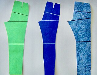
In sewing and fashion design, a pattern is the template from which the parts of a garment are traced onto woven or knitted fabrics before being cut out and assembled. Patterns are usually made of paper, and are sometimes made of sturdier materials like paperboard or cardboard if they need to be more robust to withstand repeated use. The process of making or cutting patterns is sometimes compounded to the one-word Patternmaking, but it can also be written pattern(-)making or pattern cutting.
Universal 3D (U3D) is a compressed file format standard for 3D computer graphics data.
JT is an openly-published ISO-standardized 3D CAD data exchange format used for product visualization, collaboration, digital mockups, and other purposes. It was developed by Siemens.
CAD data exchange is a method of drawing data exchange used to translate between different computer-aided design (CAD) authoring systems or between CAD and other downstream CAx systems.
Graphic design careers include creative director, art director, art production manager, brand identity developer, illustrator and layout artist.

In mechanical engineering, a fillet is a rounding of an interior or exterior corner of a part designed in CAD. An interior or exterior corner, with an angle or type of bevel, is called a "chamfer". Fillet geometry, when on an interior corner is a line of concave function, whereas a fillet on an exterior corner is a line of convex function. Fillets commonly appear on welded, soldered, or brazed joints.
Design Web Format (DWF) is a file format developed by Autodesk for the efficient distribution and communication of rich design data to anyone who needs to view, review, or print design files. Because DWF files are highly compressed, they are smaller and faster to transmit than design files, without the overhead associated with complex CAD drawings. With DWF functionality, publishers of design data can limit the specific design data and plot styles to only what they want recipients to see and can publish multisheet drawing sets from multiple AutoCAD drawings in a single DWF file. They can also publish 3D models from most Autodesk design applications.
Heinz Joseph Gerber was an American inventor and businessman. An Austrian-born Jewish Holocaust survivor who immigrated in 1940, he pioneered computer-automated manufacturing systems for an array of industries. Described as the "Thomas Edison of manufacturing", he was one of the first to recognize and develop the productivity-enhancing potential for computer automation in skill-intensive industrial sectors.

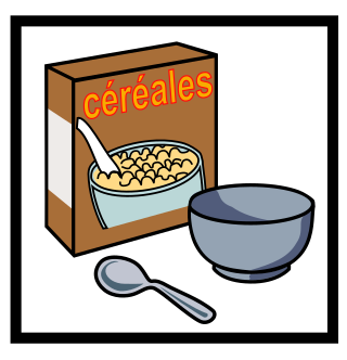
The folding carton created the packaging industry as it is known today, beginning in the late 19th century. The process involves folding carton made of paperboard that is printed, laminated, cut, then folded and glued. The cartons are shipped flat to a packager, which has its own machinery to fold the carton into its final shape as a container for a product. An example of such a carton is a cereal box.
PRC is a file format that can be used to embed 3D data in a PDF file.
Digital modeling and fabrication is a design and production process that combines 3D modeling or computing-aided design (CAD) with additive and subtractive manufacturing. Additive manufacturing is also known as 3D printing, while subtractive manufacturing may also be referred to as machining, and many other technologies can be exploited to physically produce the designed objects.
The table below provides an overview of notable computer-aided design (CAD) software. It does not judge power, ease of use, or other user-experience aspects. The table does not include software that is still in development. For all-purpose 3D programs, see Comparison of 3D computer graphics software. CAD refers to a specific type of drawing and modelling software application that is used for creating designs and technical drawings. These can be 3D drawings or 2D drawings.
Overpackaging is the use of excess packaging. The Institute of Packaging Professionals defines overpackaging as “a condition where the methods and materials used to package an item exceed the requirements for adequate containment, protection, transport, and sale”