Related Research Articles

A motherboard is the main printed circuit board (PCB) in general-purpose computers and other expandable systems. It holds and allows communication between many of the crucial electronic components of a system, such as the central processing unit (CPU) and memory, and provides connectors for other peripherals. Unlike a backplane, a motherboard usually contains significant sub-systems, such as the central processor, the chipset's input/output and memory controllers, interface connectors, and other components integrated for general use.
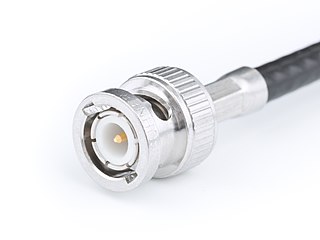
The BNC connector is a miniature quick connect/disconnect radio frequency connector used for coaxial cable. It is designed to maintain the same characteristic impedance of the cable, with 50 ohm and 75 ohm types being made. It is usually applied for video and radio frequency connections up to about 2 GHz and up to 500 volts. The connector has a twist to lock design with two lugs in the female portion of the connector engaging a slot in the shell of the male portion. The type was introduced on military radio equipment in the 1940s and has since become widely applied in radio systems, and is a common type of video connector. Similar radio-frequency connectors differ in dimensions and attachment features, and may allow for higher voltages, higher frequencies, or three-wire connections.

An RF connector is a electrical connector designed to work at radio frequencies in the multi-megahertz range. RF connectors are typically used with coaxial cables and are designed to maintain the shielding that the coaxial design offers. Better models also minimize the change in transmission line impedance at the connection in order to reduce signal reflection and power loss. As the frequency increases, transmission line effects become more important, with small impedance variations from connectors causing the signal to reflect rather than pass through. An RF connector must not allow external signals into the circuit through electromagnetic interference and capacitive pickup.

A breadboard, solderless breadboard, or protoboard is a construction base used to build semi-permanent prototypes of electronic circuits. Unlike a perfboard or stripboard, breadboards do not require soldering or destruction of tracks and are hence reusable. For this reason, breadboards are also popular with students and in technological education.

Components of an electrical circuit are electrically connected if an electric current can run between them through an electrical conductor. An electrical connector is an electromechanical device used to create an electrical connection between parts of an electrical circuit, or between different electrical circuits, thereby joining them into a larger circuit.

The D-subminiature or D-sub is a common type of electrical connector. They are named for their characteristic D-shaped metal shield. When they were introduced, D-subs were among the smallest connectors used on computer systems.

SMA connectors are semi-precision coaxial RF connectors developed in the 1960s as a minimal connector interface for coaxial cable with a screw-type coupling mechanism. The connector has a 50 Ω impedance. SMA was originally designed for use from DC (0 Hz) to 12 GHz, however this has been extended over time and variants are available to 18 GHz and 26.5 GHz. There are also mechanically compatible connectors such as the K-connector which operate up to 40 GHz. The SMA connector is most commonly used in microwave systems, hand-held radio and mobile telephone antennas and, more recently, with WiFi antenna systems and USB software-defined radio dongles. It is also commonly used in radio astronomy, particularly at higher frequencies (5 GHz+).

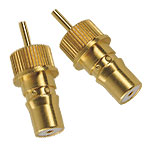
In electrical and mechanical trades and manufacturing, each half of a pair of mating connectors or fasteners is conventionally assigned the designation male or female. The female connector is generally a receptacle that receives and holds the male connector. Alternative terminology such as plug and socket or jack are sometimes used, particularly for electrical connectors.
A breakout box is a piece of electrical test equipment used to support integration testing, expedite maintenance, and streamline the troubleshooting process at the system, subsystem, and component-level by simplifying the access to test signals. Breakout boxes span a wide spectrum of functionality. Some serve to break out every signal connection coming into a unit, while others breakout only specific signals commonly monitored for either testing or troubleshooting purposes. Some have electrical connectors, and others have optical fiber connectors.
Advanced Telecommunications Computing Architecture is the largest specification effort in the history of the PCI Industrial Computer Manufacturers Group (PICMG), with more than 100 companies participating. Known as AdvancedTCA, the official specification designation PICMG 3.x was ratified by the PICMG organization in December 2002. AdvancedTCA is targeted primarily to requirements for "carrier grade" communications equipment, but has recently expanded its reach into more ruggedized applications geared toward the military/aerospace industries as well. This series of specifications incorporates the latest trends in high speed interconnect technologies, next-generation processors, and improved Reliability, Availability and Serviceability (RAS).
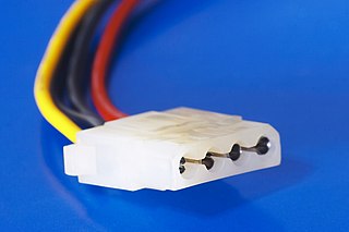
A Molex connector is a two-piece pin-and-socket interconnection which became an early electronic standard. Developed by Molex Connector Company in the late 1950s, the design features cylindrical spring-metal pins that fit into cylindrical spring-metal sockets, both held in a rectangular matrix in a nylon shell.
A SCSI connector is used to connect computer parts that use a system called SCSI to communicate with each other. Generally, two connectors, designated male and female, plug together to form a connection which allows two components, such as a computer and a disk drive, to communicate with each other. SCSI connectors can be electrical connectors or optical connectors. There have been a large variety of SCSI connectors in use at one time or another in the computer industry. Twenty-five years of evolution and three major revisions of the standards resulted in requirements for Parallel SCSI connectors that could handle an 8, 16 or 32 bit wide bus running at 5, 10 or 20 megatransfer/s, with conventional or differential signaling. Serial SCSI added another three transport types, each with one or more connector types. Manufacturers have frequently chosen connectors based on factors of size, cost, or convenience at the expense of compatibility.
Connector may refer to:

A modular connector is a type of electrical connector for cords and cables of electronic devices and appliances, such as in computer networking, telecommunication equipment, and audio headsets.
QMA and QN connectors are quick-connect RF connectors that were designed to replace the widely used SMA and Type N connectors. The connectors have been available since 2003. The connector family was created by the Quick Lock Formula Alliance, which consists of Huber+Suhner, Radiall, Rosenberger Hochfrequenztechnik, and Amphenol.

Electrical or fiber-optic connectors used by U.S. Department of Defense were originally developed in the 1930s for severe aeronautical and tactical service applications, and the Type "AN" (Army-Navy) series set the standard for modern military circular connectors. These connectors, and their evolutionary derivatives, are often called Military Standard, "MIL-STD", or (informally) "MIL-SPEC" or sometimes "MS" connectors. They are now used in aerospace, industrial, marine, and even automotive commercial applications.
Audio connectors and video connectors are electrical or optical connectors for carrying audio or video signals. Audio interfaces or video interfaces define physical parameters and interpretation of signals. For digital audio and digital video, this can be thought of as defining the physical layer, data link layer, and most or all of the application layer. For analog audio and analog video these functions are all represented in a single signal specification like NTSC or the direct speaker-driving signal of analog audio.
A torque tester is used as a quality control device to test or calibrate torque controlled tools. This includes electronic torque wrenches, click torque wrenches, dial torque wrenches, electric screwdrivers, air screwdrivers, pulse tools, cordless screwdrivers, nutrunners, and torque screwdrivers. Today's advanced torque testers include the ability to measure in clockwise and counter-clockwise directions, and potentially convert to engineering units. They can also have different modes of operation, or include a certificate from a local regulator.
The C form-factor pluggable is a multi-source agreement to produce a common form-factor for the transmission of high-speed digital signals. The c stands for the Latin letter C used to express the number 100 (centum), since the standard was primarily developed for 100 Gigabit Ethernet systems.
An optical module is a typically hot-pluggable optical transceiver used in high-bandwidth data communications applications. Optical modules typically have an electrical interface on the side that connects to the inside of the system and an optical interface on the side that connects to the outside world through a fiber optic cable. The form factor and electrical interface are often specified by an interested group using a multi-source agreement (MSA). Optical modules can either plug into a front panel socket or an on-board socket. Sometimes the optical module is replaced by an electrical interface module that implements either an active or passive electrical connection to the outside world. A large industry supports the manufacturing and use of optical modules.
References
- ↑ "BLIND MATE CONNECTORS". Positronic . Retrieved June 11, 2013.
- ↑ "SMP Board to Board RF Connectors | Amphenol RF". www.amphenolrf.com. Retrieved Sep 20, 2019.