Related Research Articles

An amplifier, electronic amplifier or (informally) amp is an electronic device that can increase the power of a signal. It is a two-port electronic circuit that uses electric power from a power supply to increase the amplitude of a signal applied to its input terminals, producing a proportionally greater amplitude signal at its output. The amount of amplification provided by an amplifier is measured by its gain: the ratio of output voltage, current, or power to input. An amplifier is a circuit that has a power gain greater than one.

A multivibrator is an electronic circuit used to implement a variety of simple two-state devices such as relaxation oscillators, timers and flip-flops. It consists of two amplifying devices cross-coupled by resistors or capacitors. The first multivibrator circuit, the astable multivibrator oscillator, was invented by Henri Abraham and Eugene Bloch during World War I. They called their circuit a "multivibrator " because its output waveform was rich in harmonics.
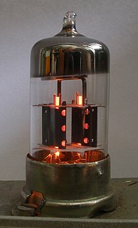
A triode is an electronic amplifying vacuum tube consisting of three electrodes inside an evacuated glass envelope: a heated filament or cathode, a grid, and a plate (anode). Developed from Lee De Forest's 1906 Audion, a partial vacuum tube that added a grid electrode to the thermionic diode, the triode was the first practical electronic amplifier and the ancestor of other types of vacuum tubes such as the tetrode and pentode. Its invention founded the electronics age, making possible amplified radio technology and long-distance telephony. Triodes were widely used in consumer electronics devices such as radios and televisions until the 1970s, when transistors replaced them. Today, their main remaining use is in high-power RF amplifiers in radio transmitters and industrial RF heating devices. In recent years there has been a resurgence in demand for low power triodes due to renewed interest in tube-type audio systems by audiophiles who prefer the pleasantly (warm) distorted sound of tube-based electronics.

A vacuum tube, electron tube, valve or tube is a device that controls electric current flow in a high vacuum between electrodes to which an electric potential difference has been applied.

A rectifier is an electrical device that converts alternating current (AC), which periodically reverses direction, to direct current (DC), which flows in only one direction. The reverse operation is performed by the inverter.
A tetrode is a vacuum tube having four active electrodes. The four electrodes in order from the centre are: a thermionic cathode, first and second grids and a plate. There are several varieties of tetrodes, the most common being the screen-grid tube and the beam tetrode. In screen-grid tubes and beam tetrodes, the first grid is the control grid and the second grid is the screen grid. In other tetrodes one of the grids is a control grid, while the other may have a variety of functions.
The Hartley oscillator is an electronic oscillator circuit in which the oscillation frequency is determined by a tuned circuit consisting of capacitors and inductors, that is, an LC oscillator. The circuit was invented in 1915 by American engineer Ralph Hartley. The distinguishing feature of the Hartley oscillator is that the tuned circuit consists of a single capacitor in parallel with two inductors in series, and the feedback signal needed for oscillation is taken from the center connection of the two inductors.

The control grid is an electrode used in amplifying thermionic valves such as the triode, tetrode and pentode, used to control the flow of electrons from the cathode to the anode (plate) electrode. The control grid usually consists of a cylindrical screen or helix of fine wire surrounding the cathode, and is surrounded in turn by the anode. The control grid was invented by Lee De Forest, who in 1906 added a grid to the Fleming valve to create the first amplifying vacuum tube, the Audion (triode).
A suppressor grid is a wire screen (grid) used in a thermionic valve to suppress secondary emission. It is also called the antidynatron grid, as it reduces or prevents dynatron oscillations. It is located between the screen grid and the plate electrode (anode). The suppressor grid is used in the pentode vacuum tube, so called because it has five concentric electrodes: cathode, control grid, screen grid, suppressor grid, and plate, and also in other tubes with more grids, such as the hexode. The suppressor grid and pentode tube were invented in 1926 by Gilles Holst and Bernard D. H. Tellegen at Phillips Electronics.

In electronics, the dynatron oscillator, invented in 1918 by Albert Hull at General Electric, is an obsolete vacuum tube electronic oscillator circuit which uses a negative resistance characteristic in early tetrode vacuum tubes, caused by a process called secondary emission. It was the first negative resistance vacuum tube oscillator. The dynatron oscillator circuit was used to a limited extent as beat frequency oscillators (BFOs), and local oscillators in vacuum tube radio receivers as well as in scientific and test equipment from the 1920s to the 1940s but became obsolete around World War 2 due to the variability of secondary emission in tubes.

A push–pull amplifier is a type of electronic circuit that uses a pair of active devices that alternately supply current to, or absorb current from, a connected load. This kind of amplifier can enhance both the load capacity and switching speed.

An electronic component is any basic discrete device or physical entity in an electronic system used to affect electrons or their associated fields. Electronic components are mostly industrial products, available in a singular form and are not to be confused with electrical elements, which are conceptual abstractions representing idealized electronic components and elements.

A pentode is an electronic device having five active electrodes. The term most commonly applies to a three-grid amplifying vacuum tube, which was invented by Gilles Holst and Bernhard D.H. Tellegen in 1926. The pentode consists of an evacuated glass envelope containing five electrodes in this order: a filament for indirectly heating a cathode, a control grid, a screen grid, a suppressor grid, and a plate (anode). The pentode was developed from the tetrode tube by the addition of a third grid, the suppressor grid. This served to prevent secondary emission electrons emitted by the plate from reaching the screen grid, which caused instability and parasitic oscillations in the tetrode. The pentode is closely related to the beam tetrode. Pentodes were widely used in industrial and consumer electronic equipment such as radios and televisions until the 1960s, when they were replaced by transistors. Their main use now is in high power industrial applications such as radio transmitters. The obsolete consumer tubes are still used in a few legacy and specialty vacuum tube audio devices.
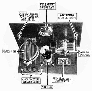
A grid leak detector is an electronic circuit that demodulates an amplitude modulated alternating current and amplifies the recovered modulating voltage. The circuit utilizes the non-linear cathode to control grid conduction characteristic and the amplification factor of a vacuum tube. Invented by Lee De Forest around 1912, it was used as the detector (demodulator) in the first vacuum tube radio receivers until the 1930s.

In electronics, a clipper is a circuit designed to prevent a signal from exceeding a predetermined reference voltage level. A clipper does not distort the remaining part of the applied waveform. Clipping circuits are used to select, for purposes of transmission, that part of a signal waveform which lies above or below the predetermined reference voltage level.
Most high power transmitter amplifiers are of valve construction because of the high power required.

A clamper is an electronic circuit that fixes either the positive or the negative peak excursions of a signal to a defined value by shifting its DC value. The clamper does not restrict the peak-to-peak excursion of the signal, it moves the whole signal up or down so as to place the peaks at the reference level. A diode clamp consists of a diode, which conducts electric current in only one direction and prevents the signal exceeding the reference value; and a capacitor, which provides a DC offset from the stored charge. The capacitor forms a time constant with the resistor load, which determines the range of frequencies over which the clamper will be effective.

In electronics, biasing is the setting of initial operating conditions of an active device in an amplifier. Many electronic devices, such as diodes, transistors and vacuum tubes, whose function is processing time-varying (AC) signals, also require a steady (DC) current or voltage at their terminals to operate correctly. This current or voltage is a bias. The AC signal applied to them is superpositioned on this DC bias current or voltage.
A magic eye tube or tuning indicator, in technical literature called an electron-ray indicator tube, is a vacuum tube which gives a visual indication of the amplitude of an electronic signal, such as an audio output, radio-frequency signal strength, or other functions. The magic eye is a specific type of such a tube with a circular display similar to the EM34 illustrated. Its first broad application was as a tuning indicator in radio receivers, to give an indication of the relative strength of the received radio signal, to show when a radio station was properly tuned in.

In electronics, a plate detector is a vacuum tube circuit in which an amplifying tube having a control grid is operated in a non-linear region of its grid voltage versus plate current transfer characteristic, usually near plate current cutoff, to demodulate amplitude modulated carrier signal. This differs from the grid leak detector, which utilizes the non-linearity of the grid voltage versus grid current characteristic for demodulation. It also differs from the diode detector, which is a two-terminal device.
References
- ↑ Cruft Electronics Staff, Electronic Circuits and Tubes, New York: McGraw-Hill, 1947, pp. 280-281, 335-336
- ↑ Ghirardi, Alfred A. (1932). Radio Physics Course (2nd ed.). New York: Rinehart Books. p. 480
- ↑ Orr, William I., ed. (1962). The Radio Handbook (16th ed.). New Augusta Indiana: Editors and Engineers, LTD. p. 266.
- 1 2 Ghirardi, Alfred A. (1932). Radio Physics Course (2nd ed.). New York: Rinehart Books. p. 475
- ↑ Ghirardi (1932) p. 476
- ↑ Cruft Electronics Staff, Electronic Circuits and Tubes, New York: McGraw-Hill, 1947, p. 335
- 1 2 3 Veley, Victor F. C. (1994). The Benchtop Electronics Reference Manual (3rd ed.). New York: Tab Books. pp. 372–374.
- ↑ Ghirardi (1932) p. 670
- ↑ Cruft Electronics Staff, 1947, p. 416
- 1 2 3 4 Tomer, Robert B. (1960). Getting the Most Out of Vacuum Tubes. Indianapolis: Howard W. Sams & Co., Inc. / The Bobbs-Merrill Company, Inc. pp. 20, 29, 62.