Charge trap flash

Last updated

Charge trap flash (CTF) is a semiconductor memory technology used in creating non-volatile NOR and NAND flash memory. It is a type of floating-gate MOSFET memory technology, but differs from the conventional floating-gate technology in that it uses a silicon nitride film to store electrons rather than the doped polycrystalline silicon typical of a floating-gate structure. This approach allows memory manufacturers to reduce manufacturing costs five ways:

Contents

  1. Fewer process steps are required to form a charge storage node
  2. Smaller process geometries can be used (therefore reducing chip size and cost)
  3. Multiple bits can be stored on a single flash memory cell
  4. Improved reliability
  5. Higher yield since the charge trap is less susceptible to point defects in the tunnel oxide layer

While the charge-trapping concept was around earlier, it wasn't until 2002 that AMD and Fujitsu produced high-volume charge-trapping flash memory. They began the commercial production of charge-trapping flash memory with the introduction of the GL NOR flash memory family. The same business, now operating under the Spansion name, has produced charge trapping devices in high volume since that time. Charge trapping flash accounted for 30% of 2008's $2.5 billion NOR flash market. Saifun Semiconductors, who licensed a large charge trapping technology portfolio to several companies, was acquired by Spansion in March 2008. From the late 2000s, CTF became a core component of 3D V-NAND flash memory developed by Toshiba and Samsung Electronics.

Origins

The original MOSFET (metal–oxide–semiconductor field-effect transistor, or MOS transistor) was invented by Egyptian engineer Mohamed M. Atalla and Korean engineer Dawon Kahng at Bell Labs in 1959, and demonstrated in 1960. [1] Kahng went on to invent the floating-gate MOSFET with Simon Min Sze at Bell Labs, and they proposed its use as a floating-gate (FG) memory cell, in 1967. [2] This was the first form of non-volatile memory based on the injection and storage of charges in a floating-gate MOSFET, [3] which later became the basis for EPROM (erasable PROM), EEPROM (electrically erasable PROM) and flash memory technologies. [4]

The charge-trapping concept was first presented by John Szedon and Ting L. Chu in 1967.[ citation needed ]

In late 1967, a Sperry research team led by H.A. Richard Wegener invented the metal–nitride–oxide–semiconductor transistor (MNOS transistor), [5] a type of MOSFET in which the oxide layer is replaced by a double layer of nitride and oxide. [6] Nitride was used as a trapping layer instead of a floating gate, but its use was limited as it was considered inferior to a floating gate. [7] The MNOS transistor device could be programmed through the application of a 50-volt forward or reverse bias between the gate and the channel to trap charges that would impact the threshold voltage of the transistor.

Charge trap (CT) memory was introduced with MNOS devices in the late 1960s. It had a device structure and operating principles similar to floating-gate (FG) memory, but the main difference is that the charges are stored in a conducting material (typically a doped polysilicon layer) in FG memory, whereas CT memory stored charges in localized traps within a dielectric layer (typically made of silicon nitride). [3]

Charge trap EEPROM

By 1974, charge trap technology was used as a storage mechanism in electrically erasable programmable read-only memory (EEPROM), and was an alternative to the standard floating-gate MOSFET technology. [8] In 1977, P.C.Y. Chen of Fairchild Camera and Instrument published a paper [9] detailing the invention of SONOS, a MOSFET technology with far less demanding program and erase conditions and longer charge storage. This improvement led to manufacturable EEPROM devices based on charge-trapping SONOS in the 1980s.

Charge trap flash experiments

In 1991, Japanese NEC researchers including N. Kodama, K. Oyama and Hiroki Shirai developed a type of flash memory that incorporated a charge trap method. [10] In 1998, Israeli engineer Boaz Eitan of Saifun Semiconductors (later acquired by Spansion) patented [11] a flash memory technology named NROM that took advantage of a charge trapping layer to replace the floating gate used in conventional flash memory designs. Two important innovations appear in this patent: the localization of the injected negative and positive charges close to the cell's drain/source terminals, and utilizing a reverse read concept to detect the cell's stored data on either end of the charge trap. These two new ideas enabled high cycling thus allowing reliable charge trap flash products to be produced for the first time since the charge trapping concept was invented 30 years earlier. Furthermore, using these concepts it is possible to create two separate physical bits per cell, doubling the capacity of stored data per cell.

In 2000, an Advanced Micro Devices (AMD) research team led by Richard M. Fastow, Egyptian engineer Khaled Z. Ahmed and Jordanian engineer Sameer Haddad (who later joined Spansion) demonstrated a charge trap mechanism for NOR flash memory cells. [12] These innovations were further improved at AMD and Fujitsu in 2002 (and later by Spansion), and first put into volume production by these companies in what was called “MirrorBit Flash memory.”

Spansion MirrorBit Flash memory

Charge trapping flash (CTF) was commercialized by AMD and Fujitsu in 2002. [13] That year, AMD (in a division later spun off as Spansion) announced a new flash memory technology it called "MirrorBit". [14] Spansion used this product to reduce manufacturing costs and extend the density range of NOR Flash memory past that of conventional NOR flash and to match the cost of the multi-level cell NOR flash being manufactured by Intel.

Spansion MirrorBit cell Fig 1 - MirrorBit.jpg
Spansion MirrorBit cell

The MirrorBit cell uses a charge trapping layer not only as a substitute for a conventional floating gate, but it also takes advantage of the non-conducting nature of the charge storage nitride to allow two bits to share the same memory cell. Shown in Figure 1 the bits reside at opposite ends of the cell and can be read by running a current through the channel in different directions.

Products have been successfully made to combine this approach with multilevel cell technology to contain four bits on a cell. [15]

Charge trapping operation

Like the floating gate memory cell, a charge trapping cell uses a variable charge between the control gate and the channel to change the threshold voltage of the transistor. The mechanisms to modify this charge are relatively similar between the floating gate and the charge trap, and the read mechanisms are also very similar.

Charge trapping vs floating gate mechanisms

In a charge trapping flash, electrons are stored in a trapping layer just as they are stored in the floating gate in a standard flash memory, EEPROM, or EPROM. The key difference is that the charge trapping layer is an insulator, while the floating gate is a conductor.

High write loads in a flash memory cause stress on the tunnel oxide layer creating small disruptions in the crystal lattice called "oxide defects". If a large number of such disruptions are created a short circuit develops between the floating gate and the transistor's channel and the floating gate can no longer hold a charge. This is the root cause of flash wear-out (see Flash memory#Memory wear), which is specified as the chip's “endurance.” In order to reduce the occurrence of such short circuits, floating gate flash is manufactured using a thick tunnel oxide (~100Å), but this slows erase when Fowler-Nordheim tunneling is used and forces the design to use a higher tunneling voltage, which puts new burdens on other parts of the chip.

A charge trapping cell is relatively immune to such difficulties, since the charge trapping layer is an insulator. [16] A short circuit created by an oxide defect between the charge trapping layer and the channel will drain off only the electrons in immediate contact with the short, leaving the other electrons in place to continue to control the threshold voltage of the transistor. Since short circuits are less of a concern, a thinner tunnel oxide layer can be used (50-70Å) increasing the trapping layer's coupling to the channel and leading to a faster program speed (with localized trapped charges) and erasing with lower tunneling voltages. The lower tunneling voltages, in turn, place less stress on the tunnel oxide layer, leading to fewer lattice disruptions.

Another important benefit of using a charge trapping cell is that the thin charge trapping layer reduces capacitive coupling between neighboring cells to improve performance and scalability. [16]

Getting the charge onto the charge trapping layer

Electrons are moved onto the charge trapping layer similarly to the way that floating gate NOR flash is programmed, through channel hot electron (CHE) injection mechanism also known as Hot-carrier injection. In brief, a high voltage is placed between the control gate while a medium-high voltage is applied on the source and the drain while a current is induced from the source to the drain. Those electrons that have gained sufficient energy in traversing through the high-field region near the drain will boil off from the channel to be injected into the charge trapping layer where they come to rest.

Removing a charge from the charge trapping layer

Charge Trapping flash is erased via hot hole injection (see Hot-carrier injection) as opposed to the Fowler–Nordheim tunneling approach used in both NAND and NOR flash for erasure. This process uses a field, rather than the current used in FN, to move holes toward the charge trapping layer to remove the charge.

Manufacturing charge trapping flash

Charge trapping flash is similar in manufacture to floating gate flash with certain exceptions that serve to simplify manufacturing.

Materials differences from floating gate

Both floating gate flash and charge trapping flash use a stacked gate structure in which a floating gate or charge trapping layer lies immediately above the channel, and below a control gate. The floating gate or charge trapping layer is insulated from the channel by a tunnel oxide layer and from the control gate by a gate oxide layer. Materials for all of these layers are the same with the exception of the storage layer, which is conductive polysilicon for the floating gate structure and is typically silicon nitride for the charge trap.

Relationship of charge trapping to silicon nanocrystals

Freescale Semiconductor manufactures a somewhat similar technology the company calls "Thin Film Storage" in its microcontroller or MCU line. The Freescale approach uses silicon nanocrystals as conductive islands in a nonconductive layer of silicon oxide.

Like the more conventional silicon nitride charge trap, electrons do not flow from one side of the floating gate to the other, extending the cell's wear.

This nanocrystal approach is being manufactured in volume by Freescale and charge trapping storage in general is in development at ST Microelectronics, Philips, Renesas, Samsung, Toshiba, Atmel, and Spansion. [17]

Process differences from Floating Gate

Since the nitride charge trapping layer is nonconductive, it does not need to be patterned – all the charge traps are already insulated from each other. This can be used to simplify manufacturing.

Floating gate structures have required more elaborate gate dielectrics for the past few process generations and today commonly use an ONO (oxide-nitride-oxide) structure which is more complex to manufacture and is unnecessary in a charge-trapping flash.

One advantage of the nitride layer is that it is less sensitive to high temperature fabrication processing than is the polysilicon used in a floating gate. This simplifies processing of the layers above the charge trap.

MirrorBit Flash memory

Spansion's MirrorBit Flash and Saifun's NROM are two flash memories that use a charge trapping mechanism in nitride to store two bits onto the same cell effectively doubling the memory capacity of a chip. This is done by placing charges on either side of the charge trap layer. The cell is read by using forward and reverse currents through the channel to read either side of the charge trap.

MirrorBit operation – getting 2 bits onto the cell

Figure 2. Programming adds electrons to the charge trap through hot electron injection. Fig 2 - Hot Electron Programming.JPG
Figure 2. Programming adds electrons to the charge trap through hot electron injection.

During CHE programming (figure 2) the hot electrons are injected from the channel into the charge trapping layer toward the biased drain end of the channel, but not from the floating source end of the channel. By allowing the transistor's source and drain to switch from one end of the channel to the other, charges can be injected and stored into the charge trapping layer over either end of the channel.

Figure 3. Erasing removes electrons from the charge trap through hot hole injection. Fig 3 - Hot Hole Erase.JPG
Figure 3. Erasing removes electrons from the charge trap through hot hole injection.

In a similar way, one end of the charge trapping cell can be erased by placing the erasing field at one end or the other of the channel, allowing the other end to float as shown in figure 3. Band-to-band Hot Hole Erase creates holes that are trapped locally some of which recombine with electrons to remove the charge from that end of the charge trap.

Reading 2 bits from the cell

The MirrorBit read is performed very simply by reversing the source and drain contacts. The junction depletion region extending from the drain side shields the channel from the charge on the side of the charge trapping cell that overlies the drain. The net result of this is that the drain-side charge has little effect on the current running through the channel, while the source-side charge determines the threshold of the transistor.

When source and drain are reversed, the opposite side's charge determines the transistor's threshold.

This way two different charge levels at either end of the charge trapping cell will cause two different currents to flow through the cell, depending on the direction of the current flow.

Later developments

Charge trapping NAND – Samsung and others

Samsung Electronics in 2006 disclosed [18] its research into the use of Charge Trapping Flash to allow continued scaling of NAND technology using cell structures similar to the planar structures in use at that time. The technology depends on a SONOS (silicon–oxide–nitride–oxide–silicon) or MONOS (metal-ONOS) capacitor structure, storing the information in charge traps in the nitride layer.

Samsung disclosed two cell structures: TANOS (Titanium, Alumina, Nitride, Oxide, Silicon) for 40 nm, where researchers believed that the existing 3D cap structure (described in detail later in this article) could not be manufactured, and THNOS, in which the aluminum oxide would be replaced with an undisclosed high-k dielectric material. The high-k material was expected to yield longer retention times than the aluminum oxide structure.

In a cap structure the control gate is extended to form a barrier between adjacent floating gates in a conventional floating gate cell.

Over the following five years many device designers found ways to push the cap structure to increasingly tighter process geometries, successfully producing NAND at the 30 nm node with this approach.

Charge trapping is still viewed as a future technology for NAND flash, but it is being considered more for vertical structures than for planar cells.

Why NAND needs charge trapping technology

Figure 4. Process shrinks over time. Fig 4 - Process History.JPG
Figure 4. Process shrinks over time.

NAND flash has been scaling very aggressively (figure 4). As processes migrate, the width of the interface of the control gate and the floating gate shrinks in proportion to the square of the shrink, and the spacing between floating gates shrinks in proportion to the process shrink, but the floating gate's thickness remains the same (the thinner the floating gate is made the less tolerant the cell becomes to electron loss). This means that the coupling between adjacent floating gates becomes larger than the coupling between the control gate and the floating gate, leading to data corruption between adjacent bits.

As processes continue to shrink, this becomes increasingly problematic. For this reason the control gate in modern NAND flash has been reconfigured to cap the floating gate. In a cap structure the control gate is extended to form a barrier between adjacent floating gates in a conventional floating gate cell (see figure 5). This serves to reduce coupling to the adjacent floating gate while increasing the coupling between the floating gate and the control gate. One drawback is that the control gate couples to the channel, so measures must be taken to minimize this coupling.

Figure 5. Capped cell structure to reduce capacitive coupling between adjacent floating gates. Fig 5 - Capped Cells.JPG
Figure 5. Capped cell structure to reduce capacitive coupling between adjacent floating gates.

It was believed in 2006 that the existing floating gate cap structure could not be manufactured at processes smaller than the 50 nm node due to difficulties in producing the complex three-layer ONO gate oxide that these devices require.

Samsung even announced [19] in late 2006 that by 2008 it would put such a device into production at the 40 nm process node, but over the five years following this announcement many device designers found ways to push the cap structure to increasingly tighter process geometries, successfully producing NAND down to 20 nm node with this approach.

The charge trapping approach is still viewed as a future for NAND flash for processes smaller than 20 nm and is being considered for both planar as well as vertical 3D structures.

When this change might occur

Today [ when? ] SanDisk asserts that the company expects to continue to use conventional NAND structures into a second node in the 10–19 nm range. [20] This implies that standard device structures could stay in place until the industry reaches 10 nm, however the challenges of producing a reliable floating gate become more severe with each process shrink.

On the other hand, the International Technology Roadmap for Semiconductors (ITRS) process technology roadmap's 2010 Process Integration, Devices, and Structures (PIDS) tables [21] show adoption of charge trapping starting at 22 nm in 2012, and becoming mainstream in 2014 with the 20 nm process.

It is possible that a planar charge trapping cell will be used for future processes. No manufacturers have yet disclosed their processes for geometries smaller than 19 nm.

Charge trapping layers for vertical structures

Vertical structures are seen as a logical next step for NAND flash, once further horizontal scaling becomes inviable. Since vertical features cannot be etched sideways, a charge trapping layer becomes a very interesting way to build a vertical NAND flash string.

Toshiba and Samsung Electronics have disclosed prototypes for vertical charge trapping NAND structures.

Toshiba's BiCS and Samsung's 3D NAND

Toshiba in 2007 [22] and Samsung in 2009 [23] announced the development of 3D V-NAND, a means of building a standard NAND flash bit string vertically rather than horizontally to increase the number of bits in a given area of silicon.

Figure 6. Vertical NAND structure. Vertical NAND Structure.svg
Figure 6. Vertical NAND structure.

A rough idea of the cross section of this is shown in figure 6. In this drawing the red portions represent conductive polysilicon, the blue is silicon dioxide insulating layers, and the yellow is the nitride charge trapping layer.

The vertical structures (only one shown) are cylinders that implement a channel that is wrapped in alternating dielectric and charge trapping layers (blue and yellow). To manufacture such a device layers of conducting polysilicon and silicon dioxide dielectric are deposited first on top of a silicon substrate that contains standard CMOS logic elements. A trench is then etched and its walls are deposited first with silicon dioxide (blue), then silicon nitride (yellow), then another silicon dioxide (blue) layer, forming the gate dielectric, the charge trap, and the tunnel dielectric in that order. Finally the hole is filled with conducting polysilicon (red) which forms the channel. The alternating layers of conductive polysilicon function as the control gates in this structure.

This structure takes advantage of the fact that the charge trap layer does not need to be insulated between each control gate, so it need not be etched in the vertical direction.

Charge trapping in embedded memories

One advantage that charge trapping flash has over other technologies is that it can be relatively easily embedded with a standard logic process. A standard logic process can be converted to a logic-plus-flash process through the addition of three more high voltage masks and three more core CTF masks, and none of these six masks is a critical layer (i.e. needs to use the most advanced part of the process). All other logic processes can be shared directly. [24]

Bandgap-Engineered Charge-Trapping Memory Devices

In ITRS PIDS 2013, it was clearly mentioned that bandgap engineered charge-trapping devices are needed to resolve the retention and erase dilemma. SONOS using a simple tunnel oxide, however, is not suitable for NAND application-once electrons are trapped in deep SiN trap levels they are difficult to detrap even under high electric field. In order to erase the device quickly holes in the substrate are injected into the SiN to neutralize the electron charge. Since the hole barrier for SiO2 is high (~4.1 eV), hole injection efficiency is poor and sufficient hole current is only achievable by using very thin tunnel oxide (~ 2 nm). Such thin tunnel oxide, however, results in poor data retention because direct hole tunneling from the substrate under the weak built-in field caused by storage electrons cannot be stopped (the rate of direct tunneling is a strong function of the barrier thickness but only weakly depends on the electric field, thus the weak built-in field by charge storage is sufficient to cause direct hole tunneling from the substrate which ruins the data retention). Several variations of SONOS have been proposed. Tunnel dielectric engineering concepts are used to modify the tunneling barrier properties to create "variable thickness" tunnel dielectric. For example, triple ultra-thin (1–2 nm) layers of ONO are introduced to replace the single oxide (BE-SONOS) [H. T. Lue, et al, IEDM 2005]. Under high electric field, the upper two layers of oxide and nitride are offset above the Si valence band, and substrate holes readily tunnel through the bottom thin oxide and inject into the thick SiN trapping layer above. In data storage mode, the weak electric field does not offset the triple layer and both electrons in the SiN and holes in the substrate are blocked by the total thickness of the triple layer. Later BE-SONOS is added high-K (Al2O3) and metal gate to enhance the erase performances, the so-called BE-MANOS [S. C. Lai, et al, NVSMW 2007]. It is suggested to add a buffer oxide in between high-K Al2O3 and SiN to improve the retention. Right now the mass production 3D NAND adopts a similar structure of BE-MANOS, with some variations of detail recipe tuning by each individual companies. The concept of bandgap engineered for tunneling barrier is recognized as a necessary path for charge-trapping devices.

Although charge trapping NAND can help the GCR and FG cross talk issues and thus promises scaling below 20nm it does not help the fundamental limitations such as word line breakdown and too few electrons. Therefore, in the roadmap trend it occupies a transition role between planar FG and 3D NAND. When charge trapping devices are used to build 3D NAND, the larger device size naturally solves the electron number and the word line breakdown issues.

Further reading

Related Research Articles

<span class="mw-page-title-main">MOSFET</span> Type of field-effect transistor

The metal–oxide–semiconductor field-effect transistor is a type of field-effect transistor (FET), most commonly fabricated by the controlled oxidation of silicon. It has an insulated gate, the voltage of which determines the conductivity of the device. This ability to change conductivity with the amount of applied voltage can be used for amplifying or switching electronic signals. The term metal–insulator–semiconductor field-effect transistor (MISFET) is almost synonymous with MOSFET. Another near-synonym is insulated-gate field-effect transistor (IGFET).

<span class="mw-page-title-main">CMOS</span> Technology for constructing integrated circuits

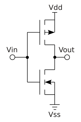
Complementary metal–oxide–semiconductor is a type of metal–oxide–semiconductor field-effect transistor (MOSFET) fabrication process that uses complementary and symmetrical pairs of p-type and n-type MOSFETs for logic functions. CMOS technology is used for constructing integrated circuit (IC) chips, including microprocessors, microcontrollers, memory chips, and other digital logic circuits. CMOS technology is also used for analog circuits such as image sensors, data converters, RF circuits, and highly integrated transceivers for many types of communication.

<span class="mw-page-title-main">Flash memory</span> Electronic non-volatile computer storage device

Flash memory is an electronic non-volatile computer memory storage medium that can be electrically erased and reprogrammed. The two main types of flash memory, NOR flash and NAND flash, are named for the NOR and NAND logic gates. Both use the same cell design, consisting of floating gate MOSFETs. They differ at the circuit level depending on whether the state of the bit line or word lines is pulled high or low: in NAND flash, the relationship between the bit line and the word lines resembles a NAND gate; in NOR flash, it resembles a NOR gate.

<span class="mw-page-title-main">EEPROM</span> Computer memory used for small quantities of data

EEPROM or E2PROM (electrically erasable programmable read-only memory) is a type of non-volatile memory. It is used in computers, usually integrated in microcontrollers such as smart cards and remote keyless systems, or as a separate chip device, to store relatively small amounts of data by allowing individual bytes to be erased and reprogrammed.

<span class="mw-page-title-main">EPROM</span> Early type of solid state computer memory

An EPROM, or erasable programmable read-only memory, is a type of programmable read-only memory (PROM) chip that retains its data when its power supply is switched off. Computer memory that can retrieve stored data after a power supply has been turned off and back on is called non-volatile. It is an array of floating-gate transistors individually programmed by an electronic device that supplies higher voltages than those normally used in digital circuits. Once programmed, an EPROM can be erased by exposing it to strong ultraviolet (UV) light source. EPROMs are easily recognizable by the transparent fused quartz window on the top of the package, through which the silicon chip is visible, and which permits exposure to ultraviolet light during erasing.

Non-volatile memory (NVM) or non-volatile storage is a type of computer memory that can retain stored information even after power is removed. In contrast, volatile memory needs constant power in order to retain data.

Reading is an action performed by computers, to acquire data from a source and place it into their volatile memory for processing. Computers may read information from a variety of sources, such as magnetic storage, the Internet, or audio and video input ports. Reading is one of the core functions of a Turing machine.

<span class="mw-page-title-main">Fin field-effect transistor</span> Type of non-planar transistor

A fin field-effect transistor (FinFET) is a multigate device, a MOSFET built on a substrate where the gate is placed on two, three, or four sides of the channel or wrapped around the channel, forming a double or even multi gate structure. These devices have been given the generic name "FinFETs" because the source/drain region forms fins on the silicon surface. The FinFET devices have significantly faster switching times and higher current density than planar CMOS technology.

In the semiconductor industry, the term high-κ dielectric refers to a material with a high dielectric constant, as compared to silicon dioxide. High-κ dielectrics are used in semiconductor manufacturing processes where they are usually used to replace a silicon dioxide gate dielectric or another dielectric layer of a device. The implementation of high-κ gate dielectrics is one of several strategies developed to allow further miniaturization of microelectronic components, colloquially referred to as extending Moore's Law.

The floating-gate MOSFET (FGMOS), also known as a floating-gate MOS transistor or floating-gate transistor, is a type of metal–oxide–semiconductor field-effect transistor (MOSFET) where the gate is electrically isolated, creating a floating node in direct current, and a number of secondary gates or inputs are deposited above the floating gate (FG) and are electrically isolated from it. These inputs are only capacitively connected to the FG. Since the FG is surrounded by highly resistive material, the charge contained in it remains unchanged for long periods of time, nowadays typically longer than 10 years. Usually Fowler-Nordheim tunneling and hot-carrier injection mechanisms are used to modify the amount of charge stored in the FG.

Hot carrier injection (HCI) is a phenomenon in solid-state electronic devices where an electron or a “hole” gains sufficient kinetic energy to overcome a potential barrier necessary to break an interface state. The term "hot" refers to the effective temperature used to model carrier density, not to the overall temperature of the device. Since the charge carriers can become trapped in the gate dielectric of a MOS transistor, the switching characteristics of the transistor can be permanently changed. Hot-carrier injection is one of the mechanisms that adversely affects the reliability of semiconductors of solid-state devices.

SONOS, short for "silicon–oxide–nitride–oxide–silicon", more precisely, "polycrystalline silicon"—"silicon dioxide"—"silicon nitride"—"silicon dioxide"—"silicon", is a cross sectional structure of MOSFET (metal–oxide–semiconductor field-effect transistor), realized by P.C.Y. Chen of Fairchild Camera and Instrument in 1977. This structure is often used for non-volatile memories, such as EEPROM and flash memories. It is sometimes used for TFT LCD displays. It is one of CTF (charge trap flash) variants. It is distinguished from traditional non-volatile memory structures by the use of silicon nitride (Si3N4 or Si9N10) instead of "polysilicon-based FG (floating-gate)" for the charge storage material. A further variant is "SHINOS" ("silicon"—"hi-k"—"nitride"—"oxide"—"silicon"), which is substituted top oxide layer with high-κ material. Another advanced variant is "MONOS" ("metal–oxide–nitride–oxide–silicon"). Companies offering SONOS-based products include Cypress Semiconductor, Macronix, Toshiba, United Microelectronics Corporation and Floadia.

nvSRAM is a type of non-volatile random-access memory (NVRAM). nvSRAM extends the functionality of basic SRAM by adding non-volatile storage such as an EEPROM to the SRAM chip. In operation, data is written to and read from the SRAM portion with high-speed access; the data in SRAM can then be stored into or retrieved from the non-volatile storage at lower speeds when needed.

The programmable metallization cell, or PMC, is a non-volatile computer memory developed at Arizona State University. PMC, a technology developed to replace the widely used flash memory, providing a combination of longer lifetimes, lower power, and better memory density. Infineon Technologies, who licensed the technology in 2004, refers to it as conductive-bridging RAM, or CBRAM. CBRAM became a registered trademark of Adesto Technologies in 2011. NEC has a variant called "Nanobridge" and Sony calls their version "electrolytic memory".

<span class="mw-page-title-main">Read-only memory</span> Electronic memory that cannot be changed

Read-only memory (ROM) is a type of non-volatile memory used in computers and other electronic devices. Data stored in ROM cannot be electronically modified after the manufacture of the memory device. Read-only memory is useful for storing software that is rarely changed during the life of the system, also known as firmware. Software applications for programmable devices can be distributed as plug-in cartridges containing ROM.

Dawon Kahng was a Korean-American electrical engineer and inventor, known for his work in solid-state electronics. He is best known for inventing the MOSFET, along with his colleague Mohamed Atalla, in 1959. Kahng and Atalla developed both the PMOS and NMOS processes for MOSFET semiconductor device fabrication. The MOSFET is the most widely used type of transistor, and the basic element in most modern electronic equipment.

<span class="mw-page-title-main">Field-effect transistor</span> Type of transistor

The field-effect transistor (FET) is a type of transistor that uses an electric field to control the flow of current in a semiconductor. It comes in two types: junction FET (JFET) and metal-oxide-semiconductor FET (MOSFET). FETs have three terminals: source, gate, and drain. FETs control the flow of current by the application of a voltage to the gate, which in turn alters the conductivity between the drain and source.

<span class="mw-page-title-main">Memory cell (computing)</span> Part of computer memory

The memory cell is the fundamental building block of computer memory. The memory cell is an electronic circuit that stores one bit of binary information and it must be set to store a logic 1 and reset to store a logic 0. Its value is maintained/stored until it is changed by the set/reset process. The value in the memory cell can be accessed by reading it.

The metal–nitride–oxide–semiconductor or metal–nitride–oxide–silicon (MNOS) transistor is a type of MOSFET in which the oxide layer is replaced by a double layer of nitride and oxide. It is an alternative and supplement to the existing standard MOS technology, wherein the insulation employed is a nitride-oxide layer. It is used in non-volatile computer memory.

<span class="mw-page-title-main">UltraRAM</span>

UltraRAM is a brand name and a storage device technology that is under development. The Physics and Engineering department of Lancaster University in collaboration with Department of Physics at Warwick published a paper in the journal of advanced electronic materials suggesting an improvement in non volatile memory technology. It has been described as a memory storage technology that "combines the non-volatility of a data storage memory, like flash, with the speed, energy-efficiency, and endurance of a working memory, like DRAM" which means it could retain data like a hard drive. While the Lancaster team performed some basic experiments to demonstrate the principles in action, UltraRAM remains mostly theoretical at the moment. The Lancaster University researchers say that further work is ongoing to improve quality, fine-tune the fabrication process, and implement and scale UltraRAM devices.

References

  1. "1960 - Metal Oxide Semiconductor (MOS) Transistor Demonstrated". The Silicon Engine. Computer History Museum.
  2. Kahng, Dawon; Sze, Simon Min (July–August 1967). "A floating gate and its application to memory devices". The Bell System Technical Journal . 46 (6): 1288–1295. Bibcode:1967ITED...14Q.629K. doi:10.1002/j.1538-7305.1967.tb01738.x.
  3. 1 2 Ioannou-Soufleridis, V.; Dimitrakis, Panagiotis; Normand, Pascal (2015). "Chapter 3: Charge-Trap Memories with Ion Beam Modified ONO Stracks". Charge-Trapping Non-Volatile Memories: Volume 1 – Basic and Advanced Devices. Springer. pp. 65–102 (65). ISBN   9783319152905.
  4. "Not just a flash in the pan". The Economist . March 11, 2006. Retrieved 10 September 2019.
  5. Wegener, H. A. R.; Lincoln, A. J.; Pao, H. C.; O'Connell, M. R.; Oleksiak, R. E.; Lawrence, H. (October 1967). The variable threshold transistor, a new electrically-alterable, non-destructive read-only storage device. 1967 International Electron Devices Meeting. Vol. 13. p. 70. doi:10.1109/IEDM.1967.187833.
  6. Brodie, Ivor; Muray, Julius J. (2013). The Physics of Microfabrication. Springer Science & Business Media. p. 74. ISBN   9781489921604.
  7. Prall, Kirk; Ramaswamy, Nirmal; Goda, Akira (2015). "Chapter 2: A Synopsis on the State of the Art of NAND Memories". Charge-Trapping Non-Volatile Memories: Volume 1 – Basic and Advanced Devices. Springer. pp. 37–64 (39). ISBN   9783319152905.
  8. Tarui, Yasuo; Nagai, Kiyoko; Hayashi, Yutaka (1974-07-19). "Nonvolatile Semiconductor Memory" (PDF). Oyo Buturi. 43 (10): 990–1002. doi:10.11470/oubutsu1932.43.990. ISSN   2188-2290. Archived (PDF) from the original on 2018-03-12.
  9. Chen, P. C. Y. (1977). "Threshold-alterable Si-gate MOS devices". IEEE Transactions on Electron Devices. 24 (5): 584–586. Bibcode:1977ITED...24..584C. doi:10.1109/T-ED.1977.18783. ISSN   0018-9383. S2CID   25586393.
  10. Kodama, N.; Oyama, K.; Shirai, H.; Saitoh, K.; Okazawa, T.; Hokari, Y. (December 1991). "A symmetrical side wall (SSW)-DSA cell for a 64 Mbit flash memory". International Electron Devices Meeting 1991 [Technical Digest]. pp. 303–306. doi:10.1109/IEDM.1991.235443. ISBN   0-7803-0243-5. S2CID   111203629.{{cite book}}: |journal= ignored (help)
  11. Eitan, Boaz. "US Patent 5,768,192: Non-volatile semiconductor memory cell utilizing asymmetrical charge trapping". US Patent & Trademark Office. Retrieved 22 May 2012.
  12. Fastow, Richard M.; Ahmed, Khaled Z.; Haddad, Sameer; et al. (April 2000). "Bake induced charge gain in NOR flash cells". IEEE Electron Device Letters. 21 (4): 184–186. Bibcode:2000IEDL...21..184F. doi:10.1109/55.830976. S2CID   24724751.
  13. "Samsung produces first 3D NAND, aims to boost densities, drive lower cost per GB". ExtremeTech . August 6, 2013. Retrieved 4 July 2019.
  14. Lammers, David (13 May 2016). "AMD pits MirrorBit against Intel StrataFlash". EE Times.
  15. "Press release "Spansion Unveils First Family of MirrorBit® Quad Solutions for Content Delivery"". Spansion, Incorporated. Archived from the original on 12 July 2012. Retrieved 22 May 2012.
  16. 1 2 Prince, Betty (2006). "Evolution of Flash Memories: Nitride Storage and Silicon Nanocrystal". CMOSET Conference Proceedings: Slide 12.
  17. Prince, Betty (2006). "Evolution of Flash Memories: Nitride Storage and Silicon Nanocrystal". CMOSET Conference Proceedings: Slide 13.
  18. Kim, Kinam; Choi, Jungdal (2006). "Future Outlook of NAND Flash Technology for 40nm Node and Beyond". IEEE Nonvolatile Semiconductor Memory Workshop Proceedings: 9–11.
  19. "Press Release: Samsung Announces First 40-nanometer Device -- 32Gb NAND Flash With Revolutionary Charge Trap Technology". Samsung. Retrieved 3 November 2013.
  20. Harari, Eli (2010). "SanDisk Financial Analyst Meeting presentation": Slide 16.{{cite journal}}: Cite journal requires |journal= (help)
  21. "ITRS Process Integration, Devices, and Structures (PIDS) Update 2010". ITRS - The International Technology Roadmap for Semiconductors. Archived from the original on 17 August 2011. Retrieved 22 May 2012.
  22. "Press Release: Toshiba Develops New NAND Flash Technology". Toshiba Corporation. Retrieved 22 May 2012.
  23. Kimura, Masahide (17 September 2009). "3D Cells Make Terabit NAND Flash Possible". Nikkei Tech-On. Archived from the original on 6 August 2012.
  24. Chung, Sung-Yong (2010). "Technology and design of charge trapping device for NOR flash application". International Memory Workshop Short Course.