A power supply is an electrical device that supplies electric power to an electrical load. The main purpose of a power supply is to convert electric current from a source to the correct voltage, current, and frequency to power the load. As a result, power supplies are sometimes referred to as electric power converters. Some power supplies are separate standalone pieces of equipment, while others are built into the load appliances that they power. Examples of the latter include power supplies found in desktop computers and consumer electronics devices. Other functions that power supplies may perform include limiting the current drawn by the load to safe levels, shutting off the current in the event of an electrical fault, power conditioning to prevent electronic noise or voltage surges on the input from reaching the load, power-factor correction, and storing energy so it can continue to power the load in the event of a temporary interruption in the source power.

A gyrator is a passive, linear, lossless, two-port electrical network element proposed in 1948 by Bernard D. H. Tellegen as a hypothetical fifth linear element after the resistor, capacitor, inductor and ideal transformer. Unlike the four conventional elements, the gyrator is non-reciprocal. Gyrators permit network realizations of two-(or-more)-port devices which cannot be realized with just the four conventional elements. In particular, gyrators make possible network realizations of isolators and circulators. Gyrators do not however change the range of one-port devices that can be realized. Although the gyrator was conceived as a fifth linear element, its adoption makes both the ideal transformer and either the capacitor or inductor redundant. Thus the number of necessary linear elements is in fact reduced to three. Circuits that function as gyrators can be built with transistors and op-amps using feedback.

A voltage regulator is a system designed to automatically maintain a constant voltage. It may use a simple feed-forward design or may include negative feedback. It may use an electromechanical mechanism, or electronic components. Depending on the design, it may be used to regulate one or more AC or DC voltages.

In electronic logic circuits, a pull-up resistor (PU) or pull-down resistor (PD) is a resistor used to ensure a known state for a signal. It is typically used in combination with components such as switches and transistors, which physically interrupt the connection of subsequent components to ground or to VCC. Closing the switch creates a direct connection to ground or VCC, but when the switch is open, the rest of the circuit would be left floating.

An electronic component is any basic discrete electronic device or physical entity part of an electronic system used to affect electrons or their associated fields. Electronic components are mostly industrial products, available in a singular form and are not to be confused with electrical elements, which are conceptual abstractions representing idealized electronic components and elements. A datasheet for an electronic component is a technical document that provides detailed information about the component's specifications, characteristics, and performance.

Capacitors are manufactured in many styles, forms, dimensions, and from a large variety of materials. They all contain at least two electrical conductors, called plates, separated by an insulating layer (dielectric). Capacitors are widely used as parts of electrical circuits in many common electrical devices.
In electronics, motorboating is a type of low frequency parasitic oscillation that sometimes occurs in audio and radio equipment and often manifests itself as a sound similar to an idling motorboat engine, a "put-put-put", in audio output from speakers or earphones. It is a problem encountered particularly in radio transceivers and older vacuum tube audio systems, guitar amplifiers, PA systems and is caused by some type of unwanted feedback in the circuit. The amplifying devices in audio and radio equipment are vulnerable to a variety of feedback problems, which can cause distinctive noise in the output. The term motorboating is applied to oscillations whose frequency is below the range of hearing, from 1 to 10 hertz, so the individual oscillations are heard as pulses. Sometimes the oscillations can even be seen visually as the woofer cones in speakers slowly moving in and out.
Ripple in electronics is the residual periodic variation of the DC voltage within a power supply which has been derived from an alternating current (AC) source. This ripple is due to incomplete suppression of the alternating waveform after rectification. Ripple voltage originates as the output of a rectifier or from generation and commutation of DC power.

In electrical engineering, a capacitor is a device that stores electrical energy by accumulating electric charges on two closely spaced surfaces that are insulated from each other. The capacitor was originally known as the condenser, a term still encountered in a few compound names, such as the condenser microphone. It is a passive electronic component with two terminals.

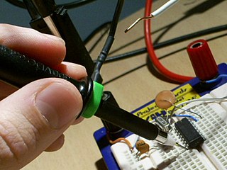
A test probe is a physical device used to connect electronic test equipment to a device under test (DUT). Test probes range from very simple, robust devices to complex probes that are sophisticated, expensive, and fragile. Specific types include test prods, oscilloscope probes and current probes. A test probe is often supplied as a test lead, which includes the probe, cable and terminating connector.

In the design of integrated circuits, power network design is the analysis and design of on-chip conductor networks that distribute electrical power on a chip. As in all engineering, this involves tradeoffs - the network must have adequate performance, be sufficiently reliable, but should not use more resources than required.
In the field of electronics, a technique where part of the output of a system is used at startup can be described as bootstrapping.

An electronic circuit is composed of individual electronic components, such as resistors, transistors, capacitors, inductors and diodes, connected by conductive wires or traces through which electric current can flow. It is a type of electrical circuit. For a circuit to be referred to as electronic, rather than electrical, generally at least one active component must be present. The combination of components and wires allows various simple and complex operations to be performed: signals can be amplified, computations can be performed, and data can be moved from one place to another.

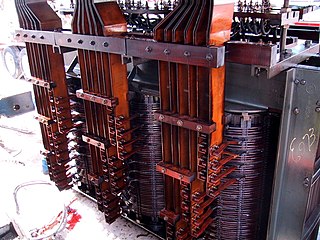
A variety of types of electrical transformer are made for different purposes. Despite their design differences, the various types employ the same basic principle as discovered in 1831 by Michael Faraday, and share several key functional parts.

Capacitors have many uses in electronic and electrical systems. They are so ubiquitous that it is rare that an electrical product does not include at least one for some purpose. Capacitors allow only AC signals to pass when they are charged blocking DC signals. The main components of filters are capacitors. Capacitors have the ability to connect one circuit segment to another. Capacitors are used by Dynamic Random Access Memory (DRAM) devices to represent binary information as bits.
Parasitic oscillation is an undesirable electronic oscillation in an electronic or digital device. It is often caused by feedback in an amplifying device. The problem occurs notably in RF, audio, and other electronic amplifiers as well as in digital signal processing. It is one of the fundamental issues addressed by control theory.
Power integrity or PI is an analysis to check whether the desired voltage and current are met from source to destination. Today, power integrity plays a major role in the success and failure of new electronic products. There are several coupled aspects of PI: on the chip, in the chip package, on the circuit board, and in the system. Four main issues must be resolved to ensure power integrity at the printed circuit board level:
- Keep the voltage ripple at the chips pads lower than the specification
- Control ground bounce
- Control electromagnetic interference and maintain electromagnetic compatibility: the power distribution network is generally the largest set of conductors on the circuit board and therefore the largest (unwanted) antenna for emission and reception of noise.
- Maintaining a proper DC voltage level at the load at high currents. A modern processor or field-programmable gate array can pull 1–100 A from a sub-1 V power rail with voltage margins in the tens of millivolts. Very little DC voltage drop can thus be tolerated on the power distribution network.

The TL431 integrated circuit (IC) is a three-terminal adjustable precise shunt voltage regulator. With the use of an external voltage divider, a TL431 can regulate voltages ranging from 2.495 to 36 V, at currents up 100 mA. The typical initial deviation of reference voltage from the nominal 2.495 V level is measured in millivolts, the maximum worst-case deviation is measured in tens of millivolts. The circuit can control power transistors directly; combinations of the TL431 with power MOS transistors are used in high efficiency, very low dropout linear regulators. The TL431 is the de facto industry standard error amplifier circuit for switched-mode power supplies with optoelectronic coupling of the input and output networks.

The NE5532, also sold as SA5532, SE5532 and NG5532 is a dual monolithic, bipolar, internally compensated operational amplifier for audio applications introduced by Signetics in 1979. The 5532 and the contemporary TL072 were the first operational amplifiers that outperformed discrete class A circuits in professional audio applications. Due to low noise and very low distortion, the 5532 became the industry standard for professional audio. According to Douglas Self, "there is probably no music on the planet that has not passed through a hundred or more 5532s on its way to the consumer". The performance of the 5532 remained best in class for almost thirty years, until the introduction of the LM4562 in 2007. As of 2021, the 5532 remains in mass production as a generic product.
This glossary of power electronics is a list of definitions of terms and concepts related to power electronics in general and power electronic capacitors in particular. For more definitions in electric engineering, see Glossary of electrical and electronics engineering. For terms related to engineering in general, see Glossary of engineering.


