An E6B flight computer commonly used by student pilots.
They are mostly used in flight training, because these flight computers have been replaced with electronic planning tools or software and websites that make these calculations for the pilots. These flight computers are used during flight planning (on the ground before takeoff) to aid in calculating fuel burn, wind correction, time en route, and other items. In the air, the flight computer can be used to calculate ground speed, estimated fuel burn and updated estimated time of arrival. The back is designed for wind vector solutions, i.e., determining how much the wind is affecting one's speed and course. They are frequently referred to by the nickname "whiz wheel".[1]
Construction
Flight computers are usually made out of aluminum, plastic or cardboard, or combinations of these materials. One side is used for wind triangle calculations using a rotating scale and a sliding panel. The other side is a circular slide rule. Extra marks and windows facilitate calculations specifically needed in aviation.
Electronic versions are also produced, resembling calculators, rather than manual slide rules. Aviation remains one of the few places that the slide rule is still in widespread use. Manual E6Bs/CRP-1s remain popular with some users and in some environments rather than the electronic ones because they are lighter, smaller, less prone to break, easy to use one-handed, quicker and do not require electrical power.
In flight training for a private pilot or instrument rating, mechanical flight computers are still often used to teach the fundamental computations. This is in part also due to the complex nature of some trigonometric calculations which would be comparably difficult to perform on a conventional scientific calculator. The graphic nature of the flight computer also helps in catching many errors which in part explains their continued popularity. The ease of use of electronic calculators means typical flight training literature[2] does not cover the use of calculators or computers at all. In the ground exams for numerous pilot ratings, programmable calculators or calculators containing flight planning software are permitted to be used.[3]
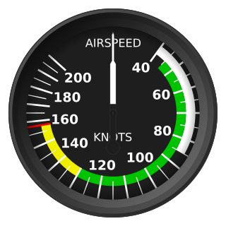
Many airspeed indicator (ASI) instruments have a movable ring built into the face of the instrument that is essentially a subset of the flight computer. Just like on the flight computer, the ring is aligned with the air temperature and the pressure altitude, allowing the true airspeed (TAS) to be read at the needle.
In addition, computer programs emulating the flight computer functions are also available, both for computers and smartphones.
Calculations
Instructions for ratio calculations and wind problems are printed on either side of the computer for reference and are also found in a booklet sold with the computer. Also, many computers have Fahrenheit to Celsius conversion charts and various reference tables.
The front side of the flight computer is a logarithmic slide rule that performs multiplication and division. Throughout the wheel, unit names are marked (such as gallons, miles, kilometers, pounds, minutes, seconds, etc.) at locations that correspond to the constants that are used when going from one unit to another in various calculations. Once the wheel is positioned to represent a certain fixed ratio (for example, pounds of fuel per hour), the rest of the wheel can be consulted to utilize that same ratio in a problem (for example, how many pounds of fuel for a 2.5-hour cruise?) This is one area where the E6B and CRP-1 are different. Since the CRP-1s are made for the UK market, they can be used to perform the added conversions of Imperial to Metric units.
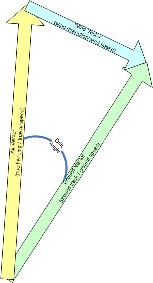
The wheel on the back of the calculator is used for calculating the effects of wind on cruise flight. A typical calculation done by this wheel answers the question: "If I want to fly on course A at a speed of B, but I encounter wind coming from direction C at a speed of D, then how many degrees must I adjust my heading, and what will my ground speed be?" This part of the calculator consists of a rotatable semi-transparent wheel with a hole in the middle, and a slide on which a grid is printed, that moves up and down underneath the wheel. The grid is visible through the transparent part of the wheel.
To solve this problem with a flight computer, first the wheel is turned so the wind direction (C) is at the top of the wheel. Then a pencil mark is made just above the hole, at a distance representing the wind speed (D) away from the hole. After the mark is made, the wheel is turned so that the course (A) is now selected at the top of the wheel. The ruler then is slid so that the pencil mark is aligned with the true airspeed (B) seen through the transparent part of the wheel. The wind correction angle is determined by matching how far right or left the pencil mark is from the hole, to the wind correction angle portion of the slide's grid. The true ground speed is determined by matching the center hole to the speed portion of the grid.
The mathematical formulas that equate to the results of the flight computer wind calculator are as follows:
(desired course is d, ground speed is Vg, heading is a, true airspeed is Va, wind direction is w, wind speed is Vw. d, a and w are angles. Vg, Va and Vw are consistent units of speed. is approximated as 355/113 or 22/7)
Wind Correction Angle:
True ground speed:
Wind Correction Angle, in degrees, as it might be programmed into a computer (which includes conversion of degrees to radians and back):
True ground speed is calculated as:
Modern-day E6Bs
Although digital E6Bs are faster to learn initially, many flight schools still require their students to learn on mechanical E6Bs,[4] and for FAA pilot written exams and checkrides pilots are encouraged to bring their mechanical E6Bs with them for necessary calculations.
History
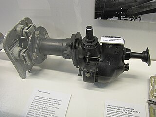
Closeup photo of a metal E-6B
The device's original name is E-6B, but is often abbreviated as E6B, or hyphenated as E6-B for commercial purposes.
Philip Dalton was a Cornell University graduate who joined the United States Army as an artillery officer, but soon resigned and became a Naval Reserve pilot from 1931 until he died in a plane crash with a student practicing spins. He, with P. V. H. Weems, invented, patented and marketed a series of flight computers.
Dalton's first popular computer was his 1933 Model B, the circular slide rule with true airspeed (TAS) and altitude corrections pilots know so well. In 1936 he put a double-drift diagram on its reverse to create what the U.S. Army Air Corps (USAAC) designated as the E-1, E-1A and E-1B.
A couple of years later he invented the Mark VII, again using his Model B slide rule as a focal point. It was hugely popular with both the military and the airlines. Fred Noonan, Amelia Earhart's navigator on her attempted circling of the globe, used one on their last flight. Dalton felt that it was a rushed design, and wanted to create something more accurate, easier to use, and able to handle higher flight speeds.
Closeup photo of a cardboard E6B
So he came up with his now famous wind arc slide, but printed on an endless cloth belt moved inside a square box by a knob. He applied for a patent in 1936 (granted in 1937 as 2,097,116). This was for the Model C, D and G computers widely used in World War II by the British Commonwealth (as the "Dalton Dead Reckoning Computer"), the U.S. Navy, copied by the Japanese, and improved on by the Germans, through Siegfried Knemeyer's invention of the disc-type Dreieckrechner device, somewhat similar to the eventual E6B's backside compass rose dial in general appearance, but having the compass rose on the front instead for real-time calculations of the wind triangle at any time while in flight. These are commonly available on collectible auction web sites.
The U.S. Army Air Corps decided the endless belt computer cost too much to manufacture, so later in 1937 Dalton morphed it to a simple, rigid, flat wind slide, with his old Model B circular slide rule included on the reverse. He called this prototype his Model H; the Army called it the E-6A.
In 1938 the Army wrote formal specifications, and had him make a few changes, which Weems called the Model J. The changes included moving the "10" mark to the top instead of the original "60". This "E-6B" was introduced to the Army in 1940, but it took Pearl Harbor for the Army Air Forces (as the former "Army Air Corps" was renamed on June 20, 1941) to place a large order. Over 400,000 E-6Bs were manufactured during World War II, mostly of a plastic that glows under black light (cockpits were illuminated this way at night).
The base name "E-6" was fairly arbitrary, as there were no standards for stock numbering at the time. For example, other USAAC computers of that time were the C-2, D-2, D-4, E-1 and G-1, and flight pants became E-1s as well. Most likely they chose "E" because Dalton's previously combined time and wind computer had been the E-1. The "B" simply meant it was the production model.
The designation "E-6B" was officially marked on the device only for a couple of years. By 1943 the Army and Navy changed the marking to their joint standard, the AN-C-74 (Army/Navy Computer 74). A year or so later it was changed to AN-5835, and then to AN-5834 (1948). The USAF called later updates the MB-4 (1953) and the CPU-26 (1958), but navigators and most instruction manuals continued using the original E-6B name. Many just called it the "Dalton Dead Reckoning Computer", one of its original markings.
Frontside of the military 6B/345Backside of the military 6B/345
After Dalton's death, Weems[5] updated the E-6B and tried calling it the E-6C, E-10, and so forth, but finally fell back on the original name, which was so well known by 50,000 World War II Army Air Force navigator veterans. After the patent ran out, many manufacturers made copies, sometimes using a marketing name of "E6-B" (note the moved hyphen). An aluminium version was made by the London Name Plate Mfg. Co. Ltd. of London and Brighton and was marked "Computer Dead Reckoning Mk. 4A Ref. No. 6B/2645" followed by the arrowhead of UK military stores.
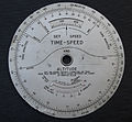
During World War II and into the early 1950s, The London Name Plate Mfg. Co. Ltd. produced a "Height & True Airspeed Computer Mk. IV" with the model reference "6B/345". The tool provided for calculation of the True Air Speed on the front side and Time-Speed calculations in relation to the altitude on the backside. They were still in use throughout the 1960s and 1970s in several European Air Forces, such as the German Air Force, until modern avionics made them obsolete.
A slide rule is a hand-operated mechanical calculator consisting of slidable rulers for evaluating mathematical operations such as multiplication, division, exponents, roots, logarithms, and trigonometry. It is one of the simplest analog computers.
In navigation, dead reckoning is the process of calculating the current position of a moving object by using a previously determined position, or fix, and incorporating estimates of speed, heading, and elapsed time. The corresponding term in biology, to describe the processes by which animals update their estimates of position or heading, is path integration.
In aerodynamics, the lift-to-drag ratio is the lift generated by an aerodynamic body such as an aerofoil or aircraft, divided by the aerodynamic drag caused by moving through air. It describes the aerodynamic efficiency under given flight conditions. The L/D ratio for any given body will vary according to these flight conditions.
The airspeed indicator (ASI) or airspeed gauge is a flight instrument indicating the airspeed of an aircraft in kilometres per hour (km/h), knots (kn), miles per hour (MPH) and/or metres per second (m/s). The recommendation by ICAO is to use km/h, however knots is currently the most used unit. The ASI measures the pressure differential between static pressure from the static port, and total pressure from the pitot tube. This difference in pressure is registered with the ASI pointer on the face of the instrument.
The basic principles of air navigation are identical to general navigation, which includes the process of planning, recording, and controlling the movement of a craft from one place to another.
In aviation, airspeed is the speed of an aircraft relative to the air it is flying through. It is difficult to measure the exact airspeed of the aircraft, but other measures of airspeed, such as indicated airspeed and Mach number give useful information about the capabilities and limitations of airplane performance. The common measures of airspeed are:
The true airspeed of an aircraft is the speed of the aircraft relative to the air mass through which it is flying. The true airspeed is important information for accurate navigation of an aircraft. Traditionally it is measured using an analogue TAS indicator, but as the Global Positioning System has become available for civilian use, the importance of such air-measuring instruments has decreased. Since indicated, as opposed to true, airspeed is a better indicator of margin above the stall, true airspeed is not used for controlling the aircraft; for these purposes the indicated airspeed – IAS or KIAS – is used. However, since indicated airspeed only shows true speed through the air at standard sea level pressure and temperature, a TAS meter is necessary for navigation purposes at cruising altitude in less dense air. The IAS meter reads very nearly the TAS at lower altitude and at lower speed. On jet airliners the TAS meter is usually hidden at speeds below 200 knots (370 km/h). Neither provides for accurate speed over the ground, since surface winds or winds aloft are not taken into account.
Indicated airspeed (IAS) is the airspeed of an aircraft as measured by its pitot-static system and displayed by the airspeed indicator (ASI). This is the pilots' primary airspeed reference.
The Norden Mk. XV, known as the Norden M series in U.S. Army service, is a bombsight that was used by the United States Army Air Forces (USAAF) and the United States Navy during World War II, and the United States Air Force in the Korean and the Vietnam Wars. It was an early tachometric design, which combined optics, a mechanical computer, and an autopilot for the first time to not merely identify a target but fly the airplane to it. The bombsight directly measured the aircraft's ground speed and direction, which older types could only estimate with lengthy manual procedures. The Norden further improved on older designs by using an analog computer that continuously recalculated the bomb's impact point based on changing flight conditions, and an autopilot that reacted quickly and accurately to changes in the wind or other effects.
Ground speed is the horizontal speed of an aircraft relative to the Earth’s surface. It is vital for accurate navigation that the pilot has an estimate of the ground speed that will be achieved during each leg of a flight.
In aviation, equivalent airspeed (EAS) is calibrated airspeed (CAS) corrected for the compressibility of air at a non-trivial Mach number. It is also the airspeed at sea level in the International Standard Atmosphere at which the dynamic pressure is the same as the dynamic pressure at the true airspeed (TAS) and altitude at which the aircraft is flying. In low-speed flight, it is the speed which would be shown by an airspeed indicator with zero error. It is useful for predicting aircraft handling, aerodynamic loads, stalling etc.
In aviation, calibrated airspeed (CAS) is indicated airspeed corrected for instrument and position error.
A bombsight is a device used by military aircraft to drop bombs accurately. Bombsights, a feature of combat aircraft since World War I, were first found on purpose-designed bomber aircraft and then moved to fighter-bombers and modern tactical aircraft as those aircraft took up the brunt of the bombing role.
In air navigation, the wind triangle is a graphical representation of the relationship between aircraft motion and wind. It is used extensively in dead reckoning navigation.
The Mark XIV Bomb Sight was a bombsight developed by Royal Air Force (RAF) Bomber Command during the Second World War. It was also known as the Blackett sight after its primary inventor, P. M. S. Blackett. Production of a slightly modified version was also undertaken in the United States as the Sperry T-1, which was interchangeable with the UK-built version. It was the RAF's standard bombsight for the second half of the war.
A slide chart is a hand-held device, usually of paper, cardboard, or plastic, for conducting simple calculations or looking up information. A circular slide chart is sometimes referred to as a wheel chart or volvelle.
Lt. Philip Dalton was a United States military scientist, pilot and engineer. Dalton is best known for his invention of several slide-rule analog flight computers, the most famous being the E6B.
A drift meter, also drift indicator and drift sight, is an optical device used to improve dead reckoning for aircraft navigation by measuring wind effect on flight.
The Course Setting Bomb Sight (CSBS) is the canonical vector bombsight, the first practical system for properly accounting for the effects of wind when dropping bombs. It is also widely referred to as the Wimperis sight after its inventor, Harry Wimperis.
A flight computer is a form of slide rule used in aviation and one of a very few analog computers in widespread use in the 21st century. Sometimes it is called by the make or model name like E6B, CR, CRP-5 or in German, as the Dreieckrechner.
This page is based on this Wikipedia article Text is available under the CC BY-SA 4.0 license; additional terms may apply. Images, videos and audio are available under their respective licenses.