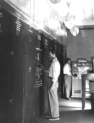
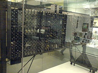
The DEUCE (Digital Electronic Universal Computing Engine) was one of the earliest British commercially available computers, built by English Electric from 1955.[1] It was the production version of the Pilot ACE, itself a cut-down version of Alan Turing's ACE.
The DEUCE had 1450 thermionic valves, and used mercurydelay lines for its main memory; each of the 12 delay lines could store 32 instructions or data words of 32 bits each. It adopted the then high 1megahertz clock rate of the Pilot ACE. Input/output was via Hollerith 80-column punch-card equipment. The reader read cards at the rate of 200 per minute, while the card punch rate was 100 cards per minute. The DEUCE also had an 8192-word magnetic drum for main storage. To access any of the 256 tracks of 32 words, the drum had one group of 16 read and one group of 16 write heads, each group on independent moveable arms, each capable of moving to one of 16 positions. Access time was 15 milliseconds if the heads were already in position; an additional 35milliseconds was required if the heads had to be moved. There was no rotational delay incurred when reading from and writing to drum. Data was transferred between the drum and one of the 32-word delay lines.
The DEUCE could be fitted with paper tape equipment; the reader speed was 850 characters per second, while the paper tape output speed was 25 characters per second. (The DEUCE at the University of New South Wales {UTECOM} had a Siemens M100 teleprinter attached in 1964, giving 10 characters per second input/output). Decca magnetic tape units could also be attached. The automatic multiplier and divider operated asynchronously (that is, other instructions could be executed while the multiplier/divider unit was in operation). Two arithmetic units were provided for integer operations: one of 32bits and another capable of performing 32-bit operations and 64-bit operations. Auto-increment and auto-decrement were provided on eight registers from about 1957. Array arithmetic and array data transfers were permitted. Compared with contemporaries such as the Manchester Mark 1, DEUCE was about ten times faster.
The individual words of the quadruple registers were associated with an auto-increment/decrement facility. That facility could be used for counting and for modifying instructions (for indexing, loop control, and for changing the source or destination address of an instruction).[2]
Being a serial machine, access time to a single register was 32microseconds, a double register 64microseconds, and a quadruple register 128microseconds. That for a delay line was 1024microseconds.
Instruction times were: addition, subtraction, logical operations: 64microseconds for 32-bit words; double-precision 96microseconds; multiplication and division 2milliseconds. For array arithmetic and transfer operations, time per word was 33microseconds per word for 32words.
Floating-point operations were provided by software; times: 6milliseconds for addition and subtraction, 5.5milliseconds average for multiplication, and 4.5milliseconds average for division.
In the early machines, all instructions involving the magnetic drum were interlocked while an operation was in progress. Thus, if the read heads were moved, any subsequent magnetics operation such as to read a track or write a track, were prohibited from proceeding until the first had completed. From about 1957, a new unit, called "rationalised magnetics" was made available. This unit eliminated unnecessary interlocks. Thus, it was possible to execute an instruction that moved the read heads: if followed by an instruction to move the write heads, or to write a track, such instructions were not interlocked, and could proceed in parallel with moving the read heads.[3]
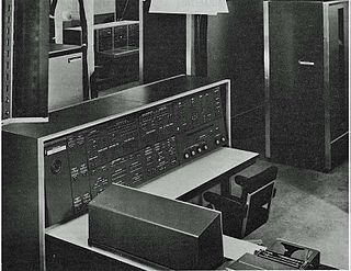
The front panel of the DEUCE featured two CRT displays: one showed the current contents of registers, while the other showed the content of any one of the mercury delay line stores.
From about 1958, seven extra delay lines could be attached, giving 224 more words of high-speed store. An IBM528 combined reader–punch could be substituted for the Hollerith equipment, giving the same input/output speeds, in which case the machine was called MarkII. Automatic conversion of alphanumeric data to BCD was provided on input, and the reverse operation on output, for all eighty card columns. On this equipment, reading and punching could proceed simultaneously, if required, and thus could be used for reading in a record, updating it, and then punching an updated record simultaneously with reading in the next record. With the seven extra delay lines, the DEUCE was denoted MarkIIA.
where "dup" duplicates the previous entry, being the same as using "y" here.
GEORGE provided a 12-position accumulator as a push-down pop-up stack. Using a variable name in a program (e.g., 'd') brought the value of variable 'd' into the accumulator (i.e., pushed d onto the top-of-stack), while enclosing a name in parentheses {e.g., (d) } assigned to variable 'd' the value at the top of the stack (accumulator). To destroy (pop and discard) the value at the top of the stack, the semicolon (;) was used. The following GEORGE program reads in ten numbers and prints their squares:
1, 10 rep (i) read dup × punch ; ]
In the above program, the "dup" command duplicated the top of the stack, so that there were then two copies of the value at the top of the stack.[6]
GIP (General Interpretive Programme) was a control program for manipulating programs called "bricks". Its principal service was in the running of programs from the several hundred in the DEUCE linear algebra library. Preparation of such a program involved selecting the required bricks (on punch cards), copying them and GIP in a reproducing punch, and assembling the copies into a deck of cards. Next, simple codewords would be written to use the bricks to perform such tasks as: matrix multiplication; matrix inversion; term-by-term matrix arithmetic (addition, subtraction, multiplication, and division); solving simultaneous equations; input; and output. The dimensions of matrices were never specified in the codewords. Dimensions were taken from the matrices themselves, either from a card preceding the data cards or from the matrices as stored on drum. Thus, programs were entirely general. Once written, such a program handled any size of matrices (up to the capacity of the drum, of course).[11] A short program to read in a matrix from cards, to transpose the matrix, and to punch the results on cards requires the following codewords:
0, 0, 5, 1 5, 0, 120, 2 120, 0, 0, 3
In each of the codewords, the fourth number is the brick number. The first codeword specifies that the matrix is read from cards and stored at drum address 5; the second codeword specifies that the matrix at drum address 5 is transposed, and the result is stored at drum address 120; and the third punches that result on cards.
STAC was a macro-assembler. Most instructions were written in the form of a transfer, in decimal, such as 13-16, meaning to copy the word in register 13 to register 16. The location of the instruction was not specified. STAC allocated an instruction to a word in a delay line, and computed the six components of the binary instruction. It allocated the next instruction to a location that was optimum, to be executed as soon as the previous instruction was complete, if possible.
The following program reads in a value, n, and then reads in n binary integers. It punches out the integer and its square. Comments in lower case explain the instruction.
1.0 12-24 start the card reader. The location of the program is specified as 1.0. 0-13X read one number (n) from the card reader. The letter X causes the computer to wait until the first row of the card has arrived at the reading station. R2 12-24 start or re-start the card reader. 0-16X read one number to be squared, store it in the multiplier register. 9-24 stop the card reader. 16-21.3 copy the number to the multiplicand register. 30-21.2 clear the low-order bits of the multiplicand register. MULT 10-24 start the card punch. 21.2-29X send the square to the card punch. 9-24 stop the card punch. 27-26 decrement n. 13-28 R1 test for zero. Branch on zero to R1; branch on not zero to R2. R1 1-1X halt; the program is complete.
STAC would produce the following instructions (in addition to the binary program). The memory location of each instruction is shown at the left.
Wait and timing numbers are not shown, except for the multiplication.
Programming
Programming the DEUCE was different from other computers. The serial nature of the delay lines required that instructions be ordered such that when one instruction completed execution, the next one was ready to emerge from a Delay Line. For operations on the single registers, the earliest time that the next instruction could be obeyed was 64 microseconds after the present one. Thus, instructions were not executed from sequential locations. In general, instructions could transfer one or more words. Consequently, each instruction specified the location of the next instruction. Optimum programming meant that as each instruction was executed, the next one was just emerging from a Delay Line. The position of instructions in the store could greatly affect performance if the location of an instruction was not optimum.
Reading data from the card reader was done in real-time – each row had to be read as it passed the read brushes, without stopping. Similarly for the card punch; the word for a particular row was prepared in advance and had to be ready when a given row of the card was in position under the punch knives. The normal mode of reading and punching was binary. Decimal input and output was performed via software.
The high-speed store consisted of four single-word registers of 32 bits each, three double-word registers, and two quadruple-word registers. Each 32-bit word of the double and quadruple-word registers could be addressed separately. They could also be accessed as a pair, and—in the case of the quadruple registers—as a group of three or four. The instruction store consisted of twelve mercury delay lines, each of 32words, and numbered 1 to 12. Delay line11 (DL11) served as the buffer between the magnetic drum and the high-speed store. Being a "transfer machine", data could be transferred a word at a time, a pair of words at a time, and any number of words up to 33 at a time. Thus, for example, 32words read from the drum could be transferred as a block to any of the other delay lines; 4words could be transferred as a block from one quadruple register to the other, or between a quadruple register and a delay line—all with one instruction. The 32words of a delay line could be summed by passing them to the single-length adder (by means of a single instruction).[12]
By a special link between DL10 and one register, namely, register16, DL10 could be used as a push-down stack.
Production
The first three machines were delivered in the spring of 1955; in late 1958 a DEUCE MarkII improved model appeared. This version employed a combined card reader and punch. The combined IBM 528 reader and punch behaved like the separate Hollerith units on the earlier DEUCE MarkI machines; however, it was also provided with hardware conversion of alphanumeric data to BCD on input, and vice versa on output. Data could also be read in and punched simultaneously at 100 cards per minute. The DEUCE MarkIIA provided seven extra mercury delay lines, each of 32words.
A total of 33 DEUCE machines were sold between 1955 and 1964, two being purchased by the engine manufacturer Bristol Siddeley.[13]
The success of DEUCE was due to its program library of over 1000 programs and subroutines.[14]
Hardware characteristics
DEUCE Mark 0 and I:
Clock rate 1 MHz Word size 32 bits High speed store 384 words Arithmetic: one 32-bit accumulator; one 64-bit accumulator that could be used also as two 32-bit accumulators. addition/subtraction 64 microseconds single length, 96 microseconds double precision Addition of a single-length number to a double-length number, with automatic sign extension, 64 microseconds. multiplication 2080 microseconds division 2112 microseconds magnetic drum 8192 words separate read heads and write heads Track read time 15 ms Head shift time 35 ms card reader speed 200 cards per minute card punch speed 100 cards per minute paper tape reader speed 850 character/second tape: 5, 7, 8-row tape. stopping time: ½ millisecond (m.s.) start time 20 milliseconds paper tape punch speed 25 characters/second tape: 5 or 7 rows Software floating-point (average times): addition/subtraction 6 m.s. multiplication 5½ m.s. division 4½ m.s.
DEUCE MARK II:
As for DEUCE Mark I. A combined IBM 528 card reader and punch could read cards at 200 per minute, and punch at 100 cards per minute. When simultaneously started, the reader and punch ran at 100 cards per minute. Automatic conversion to and from 6-bit characters was provided. This mode was in addition to the programmed conversion provided by the Mark I DEUCE.
DEUCE MARK IA AND IIA:
As above, with 7 extra delay lines providing 224 words of high-speed store.
Notes: The multiplier and divider were asynchronous. Several integers could be multiplied in a single execution of the multiply instruction, by inserting integers in the multiplier or multiplicand registers during multiplication, and by extracting results during multiplication. Other special effects included counting the bits in a word, and converting Binary Coded Decimal (BCD) to binary. Similarly for division, which could be used for converting integers to Binary Coded Decimal (BCD), and for converting pounds, shillings, and pence to pence.
In a computer's central processing unit (CPU), the accumulator is a register in which intermediate arithmetic logic unit results are stored.
EDVAC was one of the earliest electronic computers. It was built by Moore School of Electrical Engineering, Pennsylvania. Along with ORDVAC, it was a successor to the ENIAC. Unlike ENIAC, it was binary rather than decimal, and was designed to be a stored-program computer.
The IBM 1620 was announced by IBM on October 21, 1959, and marketed as an inexpensive scientific computer. After a total production of about two thousand machines, it was withdrawn on November 19, 1970. Modified versions of the 1620 were used as the CPU of the IBM 1710 and IBM 1720 Industrial Process Control Systems.
The IBM 650 Magnetic Drum Data-Processing Machine is an early digital computer produced by IBM in the mid-1950s. It was the first mass produced computer in the world. Almost 2,000 systems were produced, the last in 1962, and it was the first computer to make a meaningful profit. The first one was installed in late 1954 and it was the most-popular computer of the 1950s.
The IBM 700/7000 series is a series of large-scale (mainframe) computer systems that were made by IBM through the 1950s and early 1960s. The series includes several different, incompatible processor architectures. The 700s use vacuum-tube logic and were made obsolete by the introduction of the transistorized 7000s. The 7000s, in turn, were eventually replaced with System/360, which was announced in 1964. However the 360/65, the first 360 powerful enough to replace 7000s, did not become available until November 1965. Early problems with OS/360 and the high cost of converting software kept many 7000s in service for years afterward.
The UNIVAC LARC, short for the Livermore Advanced Research Computer, is a mainframe computer designed to a requirement published by Edward Teller in order to run hydrodynamic simulations for nuclear weapon design. It was one of the earliest supercomputers.
The IBM 1130 Computing System, introduced in 1965, was IBM's least expensive computer at that time. A binary 16-bit machine, it was marketed to price-sensitive, computing-intensive technical markets, like education and engineering, succeeding the decimal IBM 1620 in that market segment. Typical installations included a 1 megabyte disk drive that stored the operating system, compilers and object programs, with program source generated and maintained on punched cards. Fortran was the most common programming language used, but several others, including APL, were available.
The Pilot ACE was one of the first computers built in the United Kingdom. Built at the National Physical Laboratory (NPL) in the early 1950s, it was also one of the earliest general-purpose, stored-program computers – joining other UK designs like the Manchester Mark 1 and EDSAC of the same era. It was a preliminary version of the full ACE, which was designed by Alan Turing, who left NPL before the construction was completed.
The First Draft of a Report on the EDVAC is an incomplete 101-page document written by John von Neumann and distributed on June 30, 1945 by Herman Goldstine, security officer on the classified ENIAC project. It contains the first published description of the logical design of a computer using the stored-program concept, which has come to be known as the von Neumann architecture; the name has become controversial due to von Neumann's failure to name other contributors.
The IBM 305 RAMAC was the first commercial computer that used a moving-head hard disk drive for secondary storage. The system was publicly announced on September 14, 1956, with test units already installed at the U.S. Navy and at private corporations. RAMAC stood for "Random Access Method of Accounting and Control", as its design was motivated by the need for real-time accounting in business.
The APE(X)C, or All Purpose Electronic (X) Computer series was designed by Andrew Donald Booth at Birkbeck College, London in the early 1950s. His work on the APE(X)C series was sponsored by the British Rayon Research Association. Although the naming conventions are slightly unclear, it seems the first model belonged to the BRRA. According to Booth, the X stood for X-company.
The Bendix G-15 is a computer introduced in 1956 by the Bendix Corporation, Computer Division, Los Angeles, California. It is about 5 by 3 by 3 feet and weighs about 966 pounds (438 kg). The G-15 has a drum memory of 2,160 29-bit words, along with 20 words used for special purposes and rapid-access storage. The base system, without peripherals, cost $49,500. A working model cost around $60,000. It could also be rented for $1,485 per month. It was meant for scientific and industrial markets. The series was gradually discontinued when Control Data Corporation took over the Bendix computer division in 1963.
The LGP-30, standing for Librascope General Purpose and then Librascope General Precision, was an early off-the-shelf computer. It was manufactured by the Librascope company of Glendale, California, and sold and serviced by the Royal Precision Electronic Computer Company, a joint venture with the Royal McBee division of the Royal Typewriter Company. The LGP-30 was first manufactured in 1956, at a retail price of $47,000, equivalent to $510,000 in 2022.
The Metrovick 950 was a transistorized computer, built from 1956 onwards by British company Metropolitan-Vickers, to the extent of six or seven machines, which were "used commercially within the company" or "mainly for internal use". The 950 appears to have been Metrovick's first and last commercial computer offering.
The Elliott 803 is a small, medium-speed transistor digital computer which was manufactured by the British company Elliott Brothers in the 1960s. About 211 were built.
The D-37C (D37C) is the computer component of the all-inertial NS-17 Missile Guidance Set (MGS) for accurately navigating to its target thousands of miles away. The NS-17 MGS was used in the Minuteman II (LGM-30F) ICBM. The MGS, originally designed and produced by the Autonetics Division of North American Aviation, could store multiple preprogrammed targets in its internal memory.
The Bendix G-20 computer was introduced in 1961 by the Bendix Corporation, Computer Division, Los Angeles, California. The G-20 followed the highly successful G-15 vacuum-tube computer. Bendix sold its computer division to Control Data Corporation in 1963, effectively terminating the G-20.
The Manchester Mark 1 was one of the earliest stored-program computers, developed at the Victoria University of Manchester, England from the Manchester Baby. Work began in August 1948, and the first version was operational by April 1949; a program written to search for Mersenne primes ran error-free for nine hours on the night of 16/17 June 1949.
Ferranti's Sirius was a small computer released in 1961. Designed to be used in smaller offices without a dedicated programming staff, the Sirius used decimal arithmetic instead of binary, supported Autocode to ease programming, was designed to fit behind a standard office desk, and ran on UK standard mains electricity with no need for cooling. It was also fairly slow, with instruction speeds around 4,000 operations per second, and had limited main memory based on delay lines, but as Ferranti pointed out, its price/performance ratio was difficult to beat.
GEORGE is a programming language invented by Charles Leonard Hamblin in 1957. It was designed around a push-down pop-up stack for arithmetic operations, and employed reverse Polish notation. The language included loops, subroutines, conditionals, vectors, and matrices.
↑ D. G. Burnett-Hall & P. A. Samet, "A Programming Handbook for the Computer DEUCE", Royal Aircraft Establishment, Ministry of Aviation, London (England), April 1959, Technical Note M.S.38.
↑ The DEUCE at NPL was intentionally not upgraded, and the DEUCE at the University of new South Wales was not upgraded until 1963.
1 2 Hamblin, Charles Leonard (June 1957). "An addressless coding scheme based on mathematical notation". Proceedings of the First Australian Conference on Computing and Data Processing. Salisbury, South Australia: Weapons Research Establishment.
↑ Beard, Bob (Autumn 1997) [1996-10-01]. "The KDF9 Computer — 30 Years On"(PDF). Resurrection - The Bulletin of the Computer Conservation Society. No.18. Computer Conservation Society (CCS). pp.7–15. ISSN0958-7403. Archived(PDF) from the original on 27 July 2020. Retrieved 27 July 2020. […] The KDF9 is remarkable because it is the believed to be the first zero-address instruction format computer to have been announced (in 1960). It was first delivered at about the same time (early 1963) as the other famous zero-address computer, the Burroughs B5000 in America. Like many modern pocket calculators, a zero-address machine allows the use of Reverse Polish arithmetic; this offers certain advantages to compiler writers. It is believed that the attention of the English Electric team was first drawn to the zero-address concept through contact with GEORGE (General Order Generator), a high-level programming language written for a DEUCE computer by Charles Hamblin at the New South Wales University of Technology, Australia, in 1957. GEORGE used Reverse Polish, and the KDF9 team were attracted to this convention for the pragmatic reason of wishing to enhance performance by minimising accesses to main store. This may be contrasted with the more `theoretical' line taken independently by Burroughs. Besides a hardware nesting store or stack - the basic mechanism of a zero-address computer - the KDF9 had other groups of central registers for improving performance which gave it an interesting internal structure. […] (NB. This is an edited version of a talk given to North West Group of the Society at the Museum of Science and Industry, Manchester, UK on 1996-10-01.) [Quotation corrected 23 April 2021]
↑ Robinson, C. (1 April 1959). "DEUCE Interpretive Programs". The Computer Journal. 1 (4): 172–176. doi:10.1093/comjnl/1.4.172. ISSN0010-4620. Abstract: This paper describes the principal features of (i) The General Interpretive Program, (ii) The Tabular Interpretive Program, and (iii) Alphacode, which are the interpretive programs which have been most extensively used in solving problems on DEUCE. The characteristics of these three schemes are compared and contrasted.
↑ Brian Randell & L. J. Russell, "DEUCE ALGOL", Report W/AT 844, Atomic Power Division, English Electric Co., Whetstone, Leicester, England, Feb. 1962.
↑ DEUCE Library Service, "DEUCE STAC Programming Manual", English Electric Co., Ltd, Kidsgrove, Staffs, England, c. 1960.
↑ Deuce Library Service, "DEUCE General Interpretive Programme", 2nd Ed., The English Electric Company Limited, Kidsgrove, Staffs, England, c. 1963.
↑ " 'English Electric' D.E.U.C.E. Programming Manual", The English Electric Company Limited, May 1956, publication No. NS-y-16.
↑ Copeland, B. J., ed., Alan Turing's Automatic Computing Engine, Oxford: Oxford University Press, 2005, ISBN0-19-856593-3.
External links
"English Electric DEUCE computer". uraone.com. This site has an extensive collection of original documents, including programs, subroutines, DEUCE News, and bulletins.
This page is based on this Wikipedia article Text is available under the CC BY-SA 4.0 license; additional terms may apply. Images, videos and audio are available under their respective licenses.