Solid state fault current limiter
| | This section needs expansion. You can help by adding to it. (August 2015) |
A fault current limiter (FCL), also known as fault current controller (FCC), [1] is a device which limits the prospective fault current when a fault occurs (e.g. in a power transmission network) without complete disconnection. The term includes superconducting, solid-state and inductive devices. [2]
Electric power distribution systems include circuit breakers to disconnect power in case of a fault, but to maximize reliability, they wish to disconnect the smallest possible portion of the network. This means that even the smallest circuit breakers, as well as all wiring to them, must be able to disconnect large fault currents.
A problem arises if the electricity supply is upgraded, by adding new generation capacity or by adding cross-connections. Because these increase the amount of power that can be supplied, all of the branch circuits must have their bus bars and circuit breakers upgraded to handle the new higher fault current limit.
This poses a particular problem when distributed generation, such as wind farms and rooftop solar power, is added to an existing electric grid. It is desirable to be able to add additional power sources without large system-wide upgrades.
A simple solution is to add electrical impedance to the circuit. This limits the rate at which current can increase, which limits the level the fault current can rise to before the breaker is opened. However, this also limits the ability of the circuit to satisfy rapidly changing demand, so the addition or removal of large loads causes unstable power.
A fault current limiter is a nonlinear element which has a low impedance at normal current levels, but presents a higher impedance at fault current levels. Further, this change is extremely rapid, before a circuit breaker can trip a few milliseconds later. (High-power circuit breakers are synchronized to the alternating current zero crossing to minimize arcing.)
While the power is unstable during the fault, it is not completely disconnected. After the faulting branch is disconnected, the fault current limiter automatically returns to normal operation.
Superconducting fault current limiters exploit the extremely rapid loss of superconductivity (called "quenching") above a critical combination of temperature, current density, and magnetic field. In normal operation, current flows through the superconductor without resistance and negligible impedance.
If a fault develops, the superconductor quenches, its resistance rises sharply, and current is diverted to a parallel circuit with the desired higher impedance.
(The structure is not usable as a circuit breaker, because the normally-conducting superconductive material does not have a high enough resistance. It is only high enough to cause sufficient heating to melt the material.)
Superconducting fault current limiters are described as being in one of two major categories: resistive or inductive.
In a resistive FCL, the current passes directly through the superconductor. When it quenches, the sharp rise in resistance reduces the fault current from what it would otherwise be (the prospective fault current). A resistive FCL can be either DC or AC. If it is AC, then there will be a steady power dissipation from AC losses (superconducting hysteresis losses) which must be removed by the cryogenic system. An AC FCL is usually made from wire wound non-inductively; otherwise the inductance of the device would create an extra constant power loss on the system.
Inductive FCLs come in many variants, but the basic concept is a transformer with a resistive FCL as the secondary. In un-faulted operation, there is no resistance in the secondary and so the inductance of the device is low. A fault current quenches the superconductor, the secondary becomes resistive and the inductance of the whole device rises. The advantage of this design is that there is no heat ingress through current leads into the superconductor, and so the cryogenic power load may be lower. However, the large amount of iron required means that inductive FCLs are much bigger and heavier than resistive FCLs. The first successful field test of an HTS FCL of this type [ permanent dead link ] was by SC Power Systems, a division of Zenergy Power plc in 2009.
The quench process is a two-step process. First, a small region quenches directly in response to a high current density. This section rapidly heats by Joule heating, and the increase in temperature quenches adjacent regions. [ promotion? ] GridON Ltd has developed the first commercial inductive FCL for distribution & transmission networks. Using a unique and proprietary concept of magnetic-flux alteration - requiring no superconducting or cryogenic components - the self-triggered FCL instantaneously increases its impedance tenfold upon fault condition. It limits the fault current for its entire duration and recovers to its normal condition immediately thereafter. This inductive FCL is scalable to extra high voltage ratings. [3]
| | This section needs expansion. You can help by adding to it. (August 2015) |
| | This section needs expansion. You can help by adding to it. (November 2015) |
FCLs are under active development. In 2007, there were at least six national and international projects using magnesium diboride wire or YBCO tape, and two using BSCCO-2212 rods. Countries active in FCL development are Germany, the UK, the US, Korea and China. In 2007, the US Department of Energy spent $29m on three FCL development projects.
High temperature superconductors are required for practical FCLs. AC losses generate constant heat inside the superconductor, and the cost of cryogenic cooling at liquid helium temperatures required by low temperature superconductors makes the whole device uneconomic.
First applications for FCLs are likely to be used to help control medium-voltage electricity distribution systems, followed by electric-drive ships: naval vessels, submarines and cruise ships. Larger FCLs may eventually be deployed in high-voltage transmission systems.
Superconducting magnetic energy storage (SMES) systems store energy in the magnetic field created by the flow of direct current in a superconducting coil which has been cryogenically cooled to a temperature below its superconducting critical temperature. This use of superconducting coils to store magnetic energy was invented by M. Ferrier in 1970.

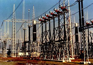
Electric power transmission is the bulk movement of electrical energy from a generating site, such as a power plant, to an electrical substation. The interconnected lines that facilitate this movement form a transmission network. This is distinct from the local wiring between high-voltage substations and customers, which is typically referred to as electric power distribution. The combined transmission and distribution network is part of electricity delivery, known as the electrical grid.

In electrical engineering, ground or earth may be a reference point in an electrical circuit from which voltages are measured, a common return path for electric current, or a direct physical connection to the Earth.
Technological applications of superconductivity include:

The electrical resistance of an object is a measure of its opposition to the flow of electric current. Its reciprocal quantity is electrical conductance, measuring the ease with which an electric current passes. Electrical resistance shares some conceptual parallels with mechanical friction. The SI unit of electrical resistance is the ohm, while electrical conductance is measured in siemens (S).
In electrical circuits, reactance is the opposition presented to alternating current by inductance and capacitance. Along with resistance, it is one of two elements of impedance; however, while both elements involve transfer of electrical energy, no dissipation of electrical energy as heat occurs in reactance; instead, the reactance stores energy until a quarter-cycle later when the energy is returned to the circuit. Greater reactance gives smaller current for the same applied voltage.

A short circuit is an electrical circuit that allows a current to travel along an unintended path with no or very low electrical impedance. This results in an excessive current flowing through the circuit. The opposite of a short circuit is an open circuit, which is an infinite resistance between two nodes.
A circuit breaker is an electrical safety device designed to protect an electrical circuit from damage caused by current in excess of that which the equipment can safely carry (overcurrent). Its basic function is to interrupt current flow to protect equipment and to prevent fire. Unlike a fuse, which operates once and then must be replaced, a circuit breaker can be reset to resume normal operation.

A superconducting magnet is an electromagnet made from coils of superconducting wire. They must be cooled to cryogenic temperatures during operation. In its superconducting state the wire has no electrical resistance and therefore can conduct much larger electric currents than ordinary wire, creating intense magnetic fields. Superconducting magnets can produce stronger magnetic fields than all but the strongest non-superconducting electromagnets, and large superconducting magnets can be cheaper to operate because no energy is dissipated as heat in the windings. They are used in MRI instruments in hospitals, and in scientific equipment such as NMR spectrometers, mass spectrometers, fusion reactors and particle accelerators. They are also used for levitation, guidance and propulsion in a magnetic levitation (maglev) railway system being constructed in Japan.
The prospective short-circuit current (PSCC), available fault current, or short-circuit making current is the highest electric current which can exist in a particular electrical system under short-circuit conditions. It is determined by the voltage and impedance of the supply system. It is of the order of a few thousand amperes for a standard domestic mains electrical installation, but may be as low as a few milliamperes in a separated extra-low voltage (SELV) system or as high as hundreds of thousands of amps in large industrial power systems. The term is used in electrical engineering rather than electronics.

A current transformer (CT) is a type of transformer that is used to reduce or multiply an alternating current (AC). It produces a current in its secondary which is proportional to the current in its primary.
In an electric power system, a switchgear is composed of electrical disconnect switches, fuses or circuit breakers used to control, protect and isolate electrical equipment. Switchgear is used both to de-energize equipment to allow work to be done and to clear faults downstream. This type of equipment is directly linked to the reliability of the electricity supply.
Inrush current, input surge current, or switch-on surge is the maximal instantaneous input current drawn by an electrical device when first turned on. Alternating-current electric motors and transformers may draw several times their normal full-load current when first energized, for a few cycles of the input waveform. Power converters also often have inrush currents much higher than their steady-state currents, due to the charging current of the input capacitance. The selection of over-current-protection devices such as fuses and circuit breakers is made more complicated when high inrush currents must be tolerated. The over-current protection must react quickly to overload or short-circuit faults but must not interrupt the circuit when the inrush current flows.

An electronic component is any basic discrete electronic device or physical entity part of an electronic system used to affect electrons or their associated fields. Electronic components are mostly industrial products, available in a singular form and are not to be confused with electrical elements, which are conceptual abstractions representing idealized electronic components and elements. A datasheet for an electronic component is a technical document that provides detailed information about the component's specifications, characteristics, and performance.
An earthing system or grounding system (US) connects specific parts of an electric power system with the ground, typically the Earth's conductive surface, for safety and functional purposes. The choice of earthing system can affect the safety and electromagnetic compatibility of the installation. Regulations for earthing systems vary among countries, though most follow the recommendations of the International Electrotechnical Commission (IEC). Regulations may identify special cases for earthing in mines, in patient care areas, or in hazardous areas of industrial plants.
Power system protection is a branch of electrical power engineering that deals with the protection of electrical power systems from faults through the disconnection of faulted parts from the rest of the electrical network. The objective of a protection scheme is to keep the power system stable by isolating only the components that are under fault, whilst leaving as much of the network as possible in operation. The devices that are used to protect the power systems from faults are called protection devices.
In an electric power system, a fault or fault current is any abnormal electric current. For example, a short circuit is a fault in which a live wire touches a neutral or ground wire. An open-circuit fault occurs if a circuit is interrupted by a failure of a current-carrying wire or a blown fuse or circuit breaker. In three-phase systems, a fault may involve one or more phases and ground, or may occur only between phases. In a "ground fault" or "earth fault", current flows into the earth. The prospective short-circuit current of a predictable fault can be calculated for most situations. In power systems, protective devices can detect fault conditions and operate circuit breakers and other devices to limit the loss of service due to a failure.
High voltage switchgear is any switchgear used to connect or disconnect a part of a high-voltage power system. This equipment is essential for the protection and safe operation, without interruption, of a high voltage power system, and is important because it is directly linked to the quality of the electricity supply.

An electric power system is a network of electrical components deployed to supply, transfer, and use electric power. An example of a power system is the electrical grid that provides power to homes and industries within an extended area. The electrical grid can be broadly divided into the generators that supply the power, the transmission system that carries the power from the generating centers to the load centers, and the distribution system that feeds the power to nearby homes and industries.
This glossary of electrical and electronics engineering is a list of definitions of terms and concepts related specifically to electrical engineering and electronics engineering. For terms related to engineering in general, see Glossary of engineering.