Gain (antenna)

Last updated

Diagram illustrating how isotropic gain is defined. The axes represent power density in watts per square meter.
R
{\displaystyle R}
is the radiation pattern of a directive antenna, which radiates a maximum power density of
S
{\displaystyle S}
watts per square meter at some given distance from the antenna. The green ball
R
iso
{\displaystyle R_{\text{iso}}}
is the radiation pattern of an isotropic antenna which radiates the same total power, and
S
iso
{\displaystyle S_{\text{iso}}}
is the power density it radiates. The gain of the first antenna is
S
S
iso
{\textstyle {S \over S_{\text{iso}}}}
. Since the directive antenna radiates the same total power within a small angle along the z axis, it can have a higher signal strength in that direction than the isotropic antenna, and so a gain greater than one. Antenna directive gain diagram.svg
Diagram illustrating how isotropic gain is defined. The axes represent power density in watts per square meter. is the radiation pattern of a directive antenna, which radiates a maximum power density of watts per square meter at some given distance from the antenna. The green ball is the radiation pattern of an isotropic antenna which radiates the same total power, and is the power density it radiates. The gain of the first antenna is . Since the directive antenna radiates the same total power within a small angle along the z axis, it can have a higher signal strength in that direction than the isotropic antenna, and so a gain greater than one.

In electromagnetics, an antenna's gain is a key performance parameter which combines the antenna's directivity and radiation efficiency. The term power gain has been deprecated by IEEE. [1] In a transmitting antenna, the gain describes how well the antenna converts input power into radio waves headed in a specified direction. In a receiving antenna, the gain describes how well the antenna converts radio waves arriving from a specified direction into electrical power. When no direction is specified, gain is understood to refer to the peak value of the gain, the gain in the direction of the antenna's main lobe. A plot of the gain as a function of direction is called the antenna pattern or radiation pattern. It is not to be confused with directivity, which does not take an antenna's radiation efficiency into account.

Contents

Gain or 'absolute gain' is defined as "The ratio of the radiation intensity in a given direction to the radiation intensity that would be produced if the power accepted by the antenna were isotropically radiated". [1] Usually this ratio is expressed in decibels with respect to an isotropic radiator (dBi). An alternative definition compares the received power to the power received by a lossless half-wave dipole antenna, in which case the units are written as dBd. Since a lossless dipole antenna has a gain of 2.15 dBi, the relation between these units is . For a given frequency, the antenna's effective area is proportional to the gain. An antenna's effective length is proportional to the square root of the antenna's gain for a particular frequency and radiation resistance. Due to reciprocity, the gain of any antenna when receiving is equal to its gain when transmitting.

Gain

Gain is a unitless measure that combines an antenna's radiation efficiency and directivity D: [1] [2] [3]

Radiation efficiency

The radiation efficiency of an antenna is "The ratio of the total power radiated by an antenna to the net power accepted by the antenna from the connected transmitter." [1]

A transmitting antenna is supplied power by a transmission line connecting the antenna to a radio transmitter. The power accepted by the antenna is the power supplied to the antenna's terminals. Losses prior to the antenna terminals are accounted for by separate impedance mismatch factors which are therefore not included in the calculation of radiation efficiency.

Gain in decibels

Published numbers for antenna gain are almost always expressed in decibels (dB), a logarithmic scale. From the gain factor G, one finds the gain in decibels as:

Therefore, an antenna with a peak power gain of 5 would be said to have a gain of 7 dBi. dBi is used rather than just dB to emphasize that this is the gain according to the basic definition, in which the antenna is compared to an isotropic radiator.

When actual measurements of an antenna's gain are made by a laboratory, the field strength of the test antenna is measured when supplied with, say, 1 watt of transmitter power, at a certain distance. That field strength is compared to the field strength found using a so-called reference antenna at the same distance receiving the same power in order to determine the gain of the antenna under test. That ratio would be equal to G if the reference antenna were an isotropic radiator (irad).

However a true isotropic radiator cannot be built, so in practice a different antenna is used. This will often be a half-wave dipole, a very well understood and repeatable antenna that can be easily built for any frequency. The directive gain of a half-wave dipole with respect to the isotropic radiator is known to be 1.64 and it can be made nearly 100% efficient. Since the gain has been measured with respect to this reference antenna, the difference in the gain of the test antenna is often compared to that of the dipole. The gain relative to a dipole is thus often quoted and is denoted using dBd instead of dBi to avoid confusion. Therefore, in terms of the true gain (relative to an isotropic radiator) G, this figure for the gain is given by:

For instance, the above antenna with a gain G = 5 would have a gain with respect to a dipole of 5/1.64 ≈ 3.05, or in decibels one would call this 10 log(3.05) ≈ 4.84 dBd. In general:

Both dBi and dBd are in common use. When an antenna's maximum gain is specified in decibels (for instance, by a manufacturer) one must be certain as to whether this means the gain relative to an isotropic radiator or with respect to a dipole. If it specifies dBi or dBd then there is no ambiguity, but if only dB is specified then the fine print must be consulted. Either figure can be easily converted into the other using the above relationship.

When considering an antenna's directional pattern, gain with respect to a dipole does not imply a comparison of that antenna's gain in each direction to a dipole's gain in that direction. Rather, it is a comparison between the antenna's gain in each direction to the peak gain of the dipole (1.64). In any direction, therefore, such numbers are 2.15 dB smaller than the gain expressed in dBi.

Partial gain

Partial gain is calculated as power gain, but for a particular polarization. It is defined as the part of the radiation intensity corresponding to a given polarization, divided by the total radiation intensity of an isotropic antenna. [2]

The partial gains in the and components are expressed as

and

,

where and represent the radiation intensity in a given direction contained in their respective field component.

As a result of this definition, we can conclude that the total gain of an antenna is the sum of partial gains for any two orthogonal polarizations.

Examples

First example

Suppose a lossless antenna has a radiation pattern given by:

Let us find the gain of such an antenna. First we find the peak radiation intensity of this antenna:

The total radiated power can be found by integrating over all directions:

Since the antenna is specified as being lossless the radiation efficiency is 1. The maximum gain is then equal to:

Expressed relative to the gain of a half-wave dipole we would find:

.

Second example

As an example, consider an antenna that radiates an electromagnetic wave whose electrical field has an amplitude at a distance That amplitude is given by:

where:

For a large distance The radiated wave can be considered locally as a plane wave. The intensity of an electromagnetic plane wave is:

where

is a universal constant called vacuum impedance.

and

If the resistive part of the series impedance of the antenna is the power fed to the antenna is The intensity of an isotropic antenna is the power so fed divided by the surface of the sphere of radius r:

The directive gain is:

For the commonly utilized half-wave dipole, the particular formulation works out to the following, including its decibel equivalency, expressed as dBi (decibels referenced to isotropic radiator):

(In most cases 73.130, is adequate)
(Likewise, 1.64 and 2.15 dBi are usually the cited values)

Sometimes, the half-wave dipole is taken as a reference instead of the isotropic radiator. The gain is then given in dBd (decibels over dipole):

0 dBd = 2.15 dBi

Realized gain

Realized gain differs from gain in that it is "reduced by its impedance mismatch factor." This mismatch induces losses above the dissipative losses described above; therefore, realized gain will always be less than gain. Gain may be expressed as absolute gain if further clarification is required to differentiate it from realized gain. [1]

Total radiated power

Total radiated power (TRP) is the sum of all RF power radiated by the antenna when the source power is included in the measurement. TRP is expressed in watts or the corresponding logarithmic expressions, often dBm or dBW. [4]

When testing mobile devices, TRP can be measured while in close proximity of power-absorbing losses such as the body and hand of the user. [5]

The TRP can be used to determine body loss (BoL). The body loss is considered as the ratio of TRP measured in the presence of losses and TRP measured while in free space.

See also

Related Research Articles

The decibel is a relative unit of measurement equal to one tenth of a bel (B). It expresses the ratio of two values of a power or root-power quantity on a logarithmic scale. Two signals whose levels differ by one decibel have a power ratio of 101/10 or root-power ratio of 10120.

In telecommunication, the free-space path loss (FSPL) is the attenuation of radio energy between the feedpoints of two antennas that results from the combination of the receiving antenna's capture area plus the obstacle-free, line-of-sight (LoS) path through free space. The "Standard Definitions of Terms for Antennas", IEEE Std 145-1993, defines free-space loss as "The loss between two isotropic radiators in free space, expressed as a power ratio." It does not include any power loss in the antennas themselves due to imperfections such as resistance. Free-space loss increases with the square of distance between the antennas because the radio waves spread out by the inverse square law and decreases with the square of the wavelength of the radio waves. The FSPL is rarely used standalone, but rather as a part of the Friis transmission formula, which includes the gain of antennas. It is a factor that must be included in the power link budget of a radio communication system, to ensure that sufficient radio power reaches the receiver such that the transmitted signal is received intelligibly.

<span class="mw-page-title-main">Radiation pattern</span> Directional variation in strength of radio waves

In the field of antenna design the term radiation pattern refers to the directional (angular) dependence of the strength of the radio waves from the antenna or other source.

<span class="mw-page-title-main">Antenna (radio)</span> Electrical device

In radio engineering, an antenna or aerial is the interface between radio waves propagating through space and electric currents moving in metal conductors, used with a transmitter or receiver. In transmission, a radio transmitter supplies an electric current to the antenna's terminals, and the antenna radiates the energy from the current as electromagnetic waves. In reception, an antenna intercepts some of the power of a radio wave in order to produce an electric current at its terminals, that is applied to a receiver to be amplified. Antennas are essential components of all radio equipment.

<span class="mw-page-title-main">Parabolic antenna</span> Type of antenna

A parabolic antenna is an antenna that uses a parabolic reflector, a curved surface with the cross-sectional shape of a parabola, to direct the radio waves. The most common form is shaped like a dish and is popularly called a dish antenna or parabolic dish. The main advantage of a parabolic antenna is that it has high directivity. It functions similarly to a searchlight or flashlight reflector to direct radio waves in a narrow beam, or receive radio waves from one particular direction only. Parabolic antennas have some of the highest gains, meaning that they can produce the narrowest beamwidths, of any antenna type. In order to achieve narrow beamwidths, the parabolic reflector must be much larger than the wavelength of the radio waves used, so parabolic antennas are used in the high frequency part of the radio spectrum, at UHF and microwave (SHF) frequencies, at which the wavelengths are small enough that conveniently sized reflectors can be used.

<span class="mw-page-title-main">Effective radiated power</span> Definition of directional radio frequency power

Effective radiated power (ERP), synonymous with equivalent radiated power, is an IEEE standardized definition of directional radio frequency (RF) power, such as that emitted by a radio transmitter. It is the total power in watts that would have to be radiated by a half-wave dipole antenna to give the same radiation intensity as the actual source antenna at a distant receiver located in the direction of the antenna's strongest beam. ERP measures the combination of the power emitted by the transmitter and the ability of the antenna to direct that power in a given direction. It is equal to the input power to the antenna multiplied by the gain of the antenna. It is used in electronics and telecommunications, particularly in broadcasting to quantify the apparent power of a broadcasting station experienced by listeners in its reception area.

<span class="mw-page-title-main">Directional antenna</span> Radio antenna which has greater performance in specific alignments

A directional antenna or beam antenna is an antenna which radiates or receives greater radio wave power in specific directions. Directional antennas can radiate radio waves in beams, when greater concentration of radiation in a certain direction is desired, or in receiving antennas receive radio waves from one specific direction only. This can increase the power transmitted to receivers in that direction, or reduce interference from unwanted sources. This contrasts with omnidirectional antennas such as dipole antennas which radiate radio waves over a wide angle, or receive from a wide angle.

<span class="mw-page-title-main">Omnidirectional antenna</span> Radio antenna that sends signals in every direction

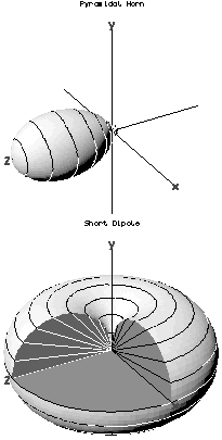
In radio communication, an omnidirectional antenna is a class of antenna which radiates equal radio power in all directions perpendicular to an axis, with power varying with angle to the axis, declining to zero on the axis. When graphed in three dimensions (see graph) this radiation pattern is often described as doughnut-shaped. This is different from an isotropic antenna, which radiates equal power in all directions, having a spherical radiation pattern. Omnidirectional antennas oriented vertically are widely used for nondirectional antennas on the surface of the Earth because they radiate equally in all horizontal directions, while the power radiated drops off with elevation angle so little radio energy is aimed into the sky or down toward the earth and wasted. Omnidirectional antennas are widely used for radio broadcasting antennas, and in mobile devices that use radio such as cell phones, FM radios, walkie-talkies, wireless computer networks, cordless phones, GPS, as well as for base stations that communicate with mobile radios, such as police and taxi dispatchers and aircraft communications.

Radiation resistance is that part of an antenna's feedpoint electrical resistance caused by the emission of radio waves from the antenna. A radio transmitter excites with a radio frequency alternating current an antenna, which radiates the exciting energy as radio waves. Because the antenna is absorbing the energy it is radiating from the transmitter, the antenna's input terminals present a resistance to the current from the transmitter.

<span class="mw-page-title-main">Dipole antenna</span> Antenna consisting of two rod shaped conductors

In radio and telecommunications a dipole antenna or doublet is the simplest and most widely used class of antenna. The dipole is any one of a class of antennas producing a radiation pattern approximating that of an elementary electric dipole with a radiating structure supporting a line current so energized that the current has only one node at each end. A dipole antenna commonly consists of two identical conductive elements such as metal wires or rods. The driving current from the transmitter is applied, or for receiving antennas the output signal to the receiver is taken, between the two halves of the antenna. Each side of the feedline to the transmitter or receiver is connected to one of the conductors. This contrasts with a monopole antenna, which consists of a single rod or conductor with one side of the feedline connected to it, and the other side connected to some type of ground. A common example of a dipole is the "rabbit ears" television antenna found on broadcast television sets.

In telecommunications, particularly in radio frequency engineering, signal strength refers to the transmitter power output as received by a reference antenna at a distance from the transmitting antenna. High-powered transmissions, such as those used in broadcasting, are expressed in dB-millivolts per metre (dBmV/m). For very low-power systems, such as mobile phones, signal strength is usually expressed in dB-microvolts per metre (dBμV/m) or in decibels above a reference level of one milliwatt (dBm). In broadcasting terminology, 1 mV/m is 1000 μV/m or 60 dBμ.

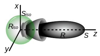
In electromagnetics and antenna theory, the aperture of an antenna is defined as "A surface, near or on an antenna, on which it is convenient to make assumptions regarding the field values for the purpose of computing fields at external points. The aperture is often taken as that portion of a plane surface near the antenna, perpendicular to the direction of maximum radiation, through which the major part of the radiation passes."

The Friis transmission formula is used in telecommunications engineering, equating the power at the terminals of a receive antenna as the product of power density of the incident wave and the effective aperture of the receiving antenna under idealized conditions given another antenna some distance away transmitting a known amount of power. The formula was presented first by Danish-American radio engineer Harald T. Friis in 1946. The formula is sometimes referenced as the Friis transmission equation.

<span class="mw-page-title-main">Isotropic radiator</span>

An isotropic radiator is a theoretical point source of waves which radiates the same intensity of radiation in all directions. It may be based on sound waves or electromagnetic waves, in which case it is also known as an isotropic antenna. It has no preferred direction of radiation, i.e., it radiates uniformly in all directions over a sphere centred on the source.

Antenna measurement techniques refers to the testing of antennas to ensure that the antenna meets specifications or simply to characterize it. Typical parameters of antennas are gain, bandwidth, radiation pattern, beamwidth, polarization, and impedance.

<span class="mw-page-title-main">Directivity</span> Measure of how much of an antennas signal is transmitted in one direction

In electromagnetics, directivity is a parameter of an antenna or optical system which measures the degree to which the radiation emitted is concentrated in a single direction. It is the ratio of the radiation intensity in a given direction from the antenna to the radiation intensity averaged over all directions. Therefore, the directivity of a hypothetical isotropic radiator is 1, or 0 dBi.

The Lee model for area-to-area mode is a radio propagation model that operates around 900 MHz. Built as two different modes, this model includes an adjustment factor that can be adjusted to make the model more flexible to different regions of propagation.

The Lee model for point-to-point mode is a radio propagation model that operates around 900 MHz. Built as two different modes, this model includes an adjustment factor that can be adjusted to make the model more flexible to different regions of propagation.

Dipole field strength in free space, in telecommunications, is the electric field strength caused by a half wave dipole under ideal conditions. The actual field strength in terrestrial environments is calculated by empirical formulas based on this field strength.

<span class="mw-page-title-main">Two-ray ground-reflection model</span>

The two-rays ground-reflection model is a multipath radio propagation model which predicts the path losses between a transmitting antenna and a receiving antenna when they are in line of sight (LOS). Generally, the two antenna each have different height. The received signal having two components, the LOS component and the reflection component formed predominantly by a single ground reflected wave.

References

  1. 1 2 3 4 5 IEEE Std 145-2013, IEEE Standard for Definitions of Terms for Antennas. IEEE.
  2. 1 2 Balanis, Constantine A. (2016). Antenna theory: analysis and design (4th ed.). Hoboken, New Jersey. p. 63. ISBN   978-1-119-17898-9. OCLC   933291646.{{cite book}}: CS1 maint: location missing publisher (link)
  3. Cheng, David K. (1992). Field and Wave Electromagnetics (Second ed.). Reading, MA: Addison-Wesley. p. 612. ISBN   0-201-12819-5.
  4. "CTIA Test Plan for Wireless Device Over-the-Air Performance Rev. 3.4.2" (PDF). Certification Test Plans. CTIA. May 2015. Archived (PDF) from the original on February 16, 2016.
  5. Mobile Broadband Multimedia Networks: Techniques, Models and Tools for 4G by Luís M. Correia

Bibliography

PD-icon.svg This article incorporates public domain material from Federal Standard 1037C. General Services Administration. Archived from the original on January 22, 2022. (in support of MIL-STD-188).