The command set consists of a series of short text strings which can be combined to produce commands for operations such as dialing, hanging up, and changing the parameters of the connection. The vast majority of dial-up modems use the Hayes command set in numerous variations.
The command set covered only those operations supported by the earliest 300 bit/s modems. When new commands were required to control additional functionality in higher speed modems, a variety of one-off standards emerged from each of the major vendors. These continued to share the basic command structure and syntax, but added any number of new commands using some sort of prefix character– & for Hayes and USR, and \ for Microcom, for instance. Many of these were re-standardized on the Hayes extensions after the introduction of the SupraFAXModem 14400 and the market consolidation that followed.
The term "Hayes compatible" was[3][1] and as of 2018 still is important within the industry.[4]
History
Background
Before the introduction of the Bulletin Board System (BBS), modems typically operated on direct-dial telephone lines that began and ended with a known modem at each end. The modems operated in either "originate" or "answer" modes, manually switching between two sets of frequencies for data transfer. Generally, the user placing the call would switch their modem to "originate" and then dial the number by hand. When the remote modem answered, already set to "answer" mode, the telephone handset was switched off and communications continued until the caller manually disconnected.
When automation was required, it was commonly only needed on the answer side; for instance, a bank might need to take calls from a number of branch offices for end-of-day processing. To fill this role, some modems included the ability to pick up the phone automatically when it was in answer mode, and to clear the line when the other user manually disconnected. The need for automated outbound dialling was considerably less common, and was handled through a separate peripheral device: a "dialler". This was normally plugged into a separate input/output port on the computer (typically an RS-232 port) and programmed separately from the modem itself.
This method of operation worked satisfactorily in the 1960s and early 1970s, when modems were generally used to connect dumb devices like computer terminals (dialling out) with smart mainframe computers (answering). However, the microcomputer revolution of the 1970s led to the introduction of low-cost modems and the idea of a semi-dedicated point-to-point link was no longer appropriate. There were potentially thousands of users who might want to dial any of the other thousands of users, and the only solution at the time was to make the user dial manually.
The computer industry needed a way to tell the modem what number to dial through software. The earlier separate dialers had this capability, but only at the cost of a separate port, which a microcomputer might not have available. Another solution would have been to use a separate set of "command pins" dedicated to sending and receiving commands, another could have used a signal pin indicating that the modem should interpret incoming data as a command. Both of these had hardware support in the RS-232 standard. However, many implementations of the RS-232 port on microcomputers were extremely basic, and some eliminated many of these pins to reduce cost.
Hayes Communications introduced a solution in its 1981 Smartmodem by using the existing data pins with no modification. Instead, the modem itself could be switched between one of two modes:
data mode in which the modem sends the data to the remote modem. (A modem in data mode treats everything it receives from the computer as data and sends it across the phone line).
command mode in which data is interpreted as commands to the local modem (commands the local modem should execute).
To switch from data mode to command mode, sessions sent an escape sequence string of three plus signs ("+++") followed by a pause of about a second. The pause at the end of the escape sequence was required to reduce the problem caused by in-band signaling: if any other data was received within one second of the three plus signs, it was not the escape sequence and would be sent as data. To switch back they sent the online command, "ATO". In actual use many of the commands automatically switched to the online mode after completion, and it is rare for a user to use the online command explicitly.
In order to avoid licensing Hayes's patent, some manufacturers implemented the escape sequence without the time guard interval (Time Independent Escape Sequence (TIES)). This had a major denial of service security implication in that it would lead to the modem hanging up the connection should the computer ever try to transmit the byte sequence "+++ATH0" in data mode. For any computer connected to the Internet through such a modem, this could be easily exploited by sending it a ping of death request containing the sequence "+++ATH0" in the payload. The computer operating system would automatically try to reply the sender with the same payload, immediately disconnecting itself from the Internet, as the modem would interpret the ICMP packet's data payload as a Hayes command.[5] The same error would also trigger if, for example, the user of the computer ever tried to send an e-mail containing the aforementioned string.
Commands
The Hayes command set includes commands for various phone-line operations such as dialing and hanging-up. It also includes various controls to set up the modem, including a set of register commands which allowed the user to directly set the various memory locations in the original Hayes modem. The command set was copied largely verbatim, including the meaning of the registers, by almost all early 300 baud modem manufacturers, of which there were quite a few.
The expansion to 1200 and 2400 baud required the addition of a small set of new commands, some of them prefixed with an ampersand ("&") to denote those dedicated to new functionality. Hayes itself was forced to quickly introduce a 2400 baud model shortly after their 1200, and the command sets were identical as a time-saving method.[6] Essentially by accident, this allowed users of existing 1200 baud modems to use the new Hayes 2400 models without changing their software. This re-inforced the use of the Hayes versions of these commands. Years later, the Telecommunications Industry Association (TIA)/Electronic Industries Alliance (EIA) raised the 2400-baud command set into a formal standard with the title Data Transmission Systems and Equipment – Serial Asynchronous Automatic Dialing and Control, TIA/EIA-602.
However, Hayes Communications were slow to release modems supporting higher speeds or compression, and three other companies led the way here— Microcom, U.S. Robotics and Telebit. Each of these three used its own additional command-sets instead of waiting for Hayes to lead the way. By the early-1990s, there were four major command sets in use, and a number of versions based on one of these. Things became simpler again during the widespread introduction of 14.4 and 28.8kbit/s modems in the early 1990s. Slowly, a set of commands based heavily on the original Hayes extended set using "&" commands became popular, and then universal. Only one other command set has remained popular, the U.S. Robotics set from their popular line of modems.
Description
The following text lists part of the Hayes command set, also called the AT commands: "AT" meaning 'attention'. Each command string is prefixed with "AT", and a number of discrete commands can be concatenated after the "AT".
The Hayes command set can subdivide into four groups:
basic command set– A capital character followed by a digit. For example, M1.
extended command set– An "&" (ampersand) and a capital character followed by a digit. This extends the basic command set. For example, &M1. Note that M1 is different from &M1.
proprietary command set– Usually starting either with a backslash (“\”) or with a percent sign (“%”); these commands vary widely among modem manufacturers.
register commands– Sr=n where r is the number of the register to be changed, and n is the new value that is assigned. A register represents a specific physical location in memory. Modems have small amounts of memory on board. The fourth set of commands serves for entering values into a particular register (memory location). For example, S7=60 instructs the modem to "Set register #7 to the value 60". Registers usually control aspects of the modem operation (e.g. transmission strength, modulation parameters) and are usually specific to a particular model.
Although the command-set syntax defines most commands by a letter-number combination (L0, L1 etc.), the use of a zero is optional. In this example, "L0" equates to a plain "L". Keep this in mind when reading the table below.
When in data mode, an escape sequence can return the modem to command mode. The normal escape sequence is three plus signs ("+++"), and to disambiguate it from possible real data, a guard timer is used: it must be preceded by a pause, not have any pauses between the plus signs, and be followed by a pause; by default, a "pause" is one second and "no pause" is anything less.
<CR> Carriage return character, is the command line and result code terminator character, which value, in decimal ASCII between 0 and 255, is specified in register S3. The default value is 13.
<LF> Linefeed character, is the character recognised as line feed character. Its value, in decimal ASCII between 0 and 255, is specified in register S4. The default value is 10. The line feed character is output after the carriage return character if verbose result codes are used (V1 option is used); otherwise, if numeric format result codes are used (V0 option is used), it will not appear in the result codes.
<...> Name enclosed in angle brackets is a syntactical element. They do not appear in the command line.
[...] Optional subparameter of a command or an optional part of AT information response is enclosed in square brackets. Brackets themselves do not appear in the command line. When the subparameter is not given in AT commands which have a Read command, the new value equals its previous value. In AT commands which do not store the values of any of their subparameters, and so have not a Read command, which are called action type commands, the action should be done on the basis of the recommended default setting of the subparameter.
Modem initialization
A string can contain many Hayes commands placed together, so as to optimally prepare the modem to dial out or answer, e.g. AT&F&D2&C1S0=0X4. Most modem software supported a user supplied initialization string, which was typically a long concatenated AT command which was sent to the modem upon launch.[8] The V.250 specification requires all DCEs to accept a body (after "AT") of at least 40 characters of concatenated commands.[9]
Example session
The following represents two computers, computer A and computer B, both with modems attached, and the user controlling the modems with terminal-emulator software. Terminal-emulator software typically allows the user to send Hayes commands directly to the modem, and to see the responses. In this example, the user of computer A makes the modem dial the phone number of modem B at phone number (212) 555-0100 (long distance). After every command and response, there is a carriage return sent to complete the command.
Modem A
Modem B
Comment
ATDT12125550100
User at modem A issues a dial command: AT-Get the modem's ATtention; D-Dial; T-Touch-Tone; 12125550100-Call this number
RING
Modem A begins dialing. Modem B's phone-line rings, and the modem reports the fact.
ATA
Computer at modem B issues answer command.
CONNECT
CONNECT
The modems connect, and both modems report "connect". (In practice, most modems report more information after the word CONNECT — specifying the speed of the connection.) Also, at this time, both modems will raise the DCD, or Data Carrier Detect signal, on the serial port.
abcdef
abcdef
When the modems are connected, any characters typed at either side will appear on the other side. The person at computer A starts typing. The characters pass through the modem and appear on computer B's screen. (User A may not see his own typed characters — depending on the terminal software's local echo setting).
+++
The person at computer B issues the modem escape command. (Alternately, and more commonly, the computer B could drop the DTR, or Data Terminal Ready signal, to achieve a hangup, without needing to use +++ or ATH.)
OK
The modem acknowledges it.
ATH
The person at computer B issues a hang up command.
NO CARRIER
OK
Both modems report that the connection has ended. Modem B responds "OK" as the expected result of the command; modem A says NO CARRIER to report that the remote side interrupted the connection. The modems on both sides drop their DCD signals as well.
Compatibility
While the original Hayes command set represented a huge leap forward in modem-based communications, with time many problems set in, almost none of them due to Hayes per se:
Due to the lack of a written standard, other modem manufacturers just copied the external visible commands and (roughly) the basic actions. This led to a wide variety of subtle differences in how modems changed from state to state, and how they handled error conditions, hangups, and timeouts.
Each manufacturer tended to add new commands to handle emerging needs, often incompatible with other modems. For example, setting up hardware or software handshaking often required many different commands for different modems. This undermined the handy universality of the basic Hayes command set.
Many Hayes compatible modems had serious quirks that made them effectively incompatible. For example, many modems required a pause of several seconds after receiving the "AT Z" reset command. Some modems required spaces between commands, while others did not. Some would unhelpfully change baud-rate of their own volition, which would leave the computer with no clue how to handle the incoming data.
As a result of all this, eventually many communications programs had to give up any sense of being able to talk to all "Hayes-compatible" modems, and instead the programs had to try to determine the modem type from its responses, or provide the user with some option whereby they could enter whatever special commands it took to coerce their particular modem into acting properly.
Autobaud
The Hayes command set facilitated automatic baud rate detection as "A" and "T" happen to have bit patterns that are very regular; "A" is "100 0001" and so has a 1 bit at the start and end and "T" is "101 0100" which has a pattern with (nearly) every other bit set.[10] Since the RS-232 interface transmits least significant bit first, the according line pattern with 8-N-1 (eight data bits, no parity bit, one stop bit) is 01000001010001010101 (start and stop bits italicized) which is used as syncword.
The basic Hayes command set
The following commands are understood by virtually all modems supporting an AT command set, whether old or new.
Command
Description
Comments
A0 or A
Answer incoming call
A/
Repeat last command
Do not preface with AT, do not follow with carriage return. Enter usually aborts.
D
Dial
Dial the following number and then handshake
P – Pulse Dial T – Touch Tone Dial W – Wait for the second dial tone R – Reverse to answer-mode after dialing @ - Wait for up to 30 seconds for one or more ringbacks , - Pause for the time specified in register S8 (usually 2 seconds) ; – Remain in command mode after dialing. ! – Flash switch-hook (Hang up for a half second, as in transferring a call.) L – Dial last number
E0 or E
No Echo
Will not echo commands to the computer
E1
Echo
Will echo commands to the computer (so one can see what one types if the computer software does not support echo)
H0 or H
Hook Status
On hook. Hangs up the phone, ending any call in progress.
H1
Hook status
Off hook. Picks up the phone line (typically you'll hear a dialtone)
I0 to I9
Inquiry, Information, or Interrogation
This command returns information about the model, such as its firmware or brand name. Each number (0 to 9, and sometimes 10 and above) returns one line of modem-specific information, or the word ERROR if the line is not defined. Today, Windows uses this for Plug-and-play detection of specific modem types.
L0 or Ln (n=1 to 3)
Speaker Loudness. Supported only by some modems with speakers. Modems lacking speakers, or with physical volume controls, or ones whose sound output is piped through the sound card will not support this command.
0 turns off speaker, 1 to 3 are for increasing volumes.
M0 or M
Speaker Mute, completely silent during dialing
M3 is also common, but different on many brands
M1
Speaker on until remote carrier detected (user will hear dialing and the modem handshake, but once a full connection is established the speaker is muted)
M2
Speaker always on (data sounds are heard after CONNECT)
O
Return Online
Returns the modem back to the normal connected state after being interrupted by the "+++" escape code.
Q0 or Q
Quiet Mode
Off – Displays result codes, user sees command responses (e.g. OK)
Q1
Quiet Mode
On – Result codes are suppressed, user does not see responses.
Sn
Select current register
Note that Sn, ? and =r are actually three separate commands, and can be given in separate AT commands.
Select register n as the current register
Sn?
Select register n as the current register, and query its value. Using ? on its own will query whichever register was most recently selected.
Sn=r
Select register n as the current register, and store r in it. Using =r on its own will store into whichever register was most recently selected.
V0 or V
Verbose
Numeric result codes
V1
English result codes (e.g. CONNECT, BUSY, NO CARRIER etc.)
X0 or X
Smartmodem
Hayes Smartmodem 300 compatible result codes
X1
Usually adds connection speed to basic result codes (e.g. CONNECT 1200)
X2
Usually adds dial tone detection (preventing blind dial, and sometimes preventing ATO)
X3
Usually adds busy signal detection.
X4
Usually adds both busy signal and dial tone detection
Z0 or Z
Reset
Reset modem to stored configuration, and usually also physically power-cycles the modem (during which it is unresponsive). Z0', Z1 etc. are for multiple stored profiles. &F is similar in that it returns to factory default settings on modems without NVRAM (non volatile memory), but it does not reset the modem
Note: a command string is terminated with a CR (\r) character
Although not part of the command set, a tilde character ~ is commonly used in modem command sequences. The ~ causes many applications to pause sending the command stream to the device (usually for half a second), e.g. after a Reset. The ~ is not sent to the modem.[11]
Modem S register definitions
Register
Description
Range
Default value
S0
Number of rings before Auto-Answer
0–255 (0 = never)
0
S1
Ring Counter
0–255 rings
0
S2
Escape character
0–255, ASCII decimal
43 ("+")
S3
Carriage Return Character
0–127, ASCII decimal
13 (Carriage Return)
S4
Line Feed Character
0–127, ASCII decimal
10 (Line Feed)
S5
Backspace Character
0–32, ASCII decimal
8 (Backspace)
S6
Wait Time before Blind Dialing
2–255 seconds
2
S7
Wait for Carrier after Dial
1–255 seconds
50
S8
Pause Time for Comma (Dial Delay)
0–255 seconds
2
S9
Carrier Detect Response Time
1–255 tenths of a seconds
6 (0.6 second)
S10
Delay between Loss of Carrier and Hang-Up
1–255 tenths of a second
14 (1.4 seconds)
S11
DTMF Tone Duration
50–255 milliseconds
95 milliseconds
S12
Escape Code Guard Time
0–255 fiftieths of a second
50 (1 second)
S18
Test Timer
0–255 seconds
0 seconds
S25
Delay to DTR
0–255 (seconds if synchronous mode, hundredths of a second in all other modes)
5
S26
RTS to CTS Delay Interval
0–255 hundredths of a second
1 hundredth of a second
S30
Inactivity Disconnect Timer
0–255 tens of seconds
0 (disable)
S37
Desired Telco Line Speed
0–10
Command options:
0 Attempt auto mode connection
1 Attempt to connect at 300 bit/s
2 Attempt to connect at 300 bit/s
3 Attempt to connect at 300 bit/s
5 Attempt to connect at 1200 bit/s
6 Attempt to connect at 2400 bit/s
7 Attempt to connect in V.23 75/1200 mode.
8 Attempt to connect at 9600 bit/s
9 Attempt to connect at 12000 bit/s
10 Attempt to connect at 14400 bit/s
0
S38
Delay before Force Disconnect
0–255 seconds
20 seconds
V.250
The ITU-T established a standard in its V-Series Recommendations, V.25 ter, in 1995 in an attempt to establish a standard for the command set again. It was renamed V.250 in 1998 with an annex that was not concerning the Hayes command set renamed as V.251. A V.250 compliant modem implements the A, D, E, H, I, L, M, N, O, P, Q, T, V, X, Z, &C, &D, and &F commands in the way specified by the standard. It must also implement S registers and must use registers S0, S3, S4, S5, S6, S7, S8, and S10 for the purposes given in the standard. It also must implement any command beginning with the plus sign, "+" followed by any letter A to Z, only in accordance with ITU recommendations. Modem manufacturers are free to implement other commands and S-registers as they see fit, and may add options to standard commands.
V.250 – Defined leading character sequences
Leading characters
Includes commands related to
+A
Call control (network Addressing) issues, common, PSTN, ISDN, ITU-T Rec. X.25, switched digital
+C
Digital Cellular extensions
+D
Data Compression, ITU-T Rec. V.42 bis
+E
Error Control, ITU-T Rec. V.42
+F
Facsimile, ITU-T Rec. T.30, etc.
+G
Generic issues such as identity and capabilities
+I
DTE-DCE Interface issues, ITU-T Rec. V.24, etc.
+M
Modulation, ITU-T Rec. V.32 bis, etc.
+P
PCM DCE commands, ITU-T Rec. V.92
+S
Switched or Simultaneous Data Types
+T
Test issues
+V
Voice extensions
+W
Wireless extensions
GSM
The ETSI GSM 07.07 (3GPP TS 27.007) specifies AT style commands for controlling a GSM phone or modem. The ETSI GSM 07.05 (3GPP TS 27.005) specifies AT style commands for managing the Short Message Service (SMS) feature of GSM.
GSM/3G modems typically support the ETSI GSM 07.07/3GPP TS 27.007 AT command set extensions, although how many commands are implemented varies.
Most USB modem vendors, such as Huawei, Sierra Wireless, Option, have also defined proprietary extensions for radio mode selection (GSM/3G preference) or similar. Some recent high speed modems provide a virtual Ethernet interface instead of using a Point-to-Point Protocol (PPP) for the data connection because of performance reasons (PPP connection is only used between the computer and the modem, not over network). The set-up requires vendor-specific AT command extensions. Sometimes the specifications for these extensions are openly available, other times the vendor requires an NDA for access to these.[14]
General Packet Radio Service (GPRS), also called 2.5G, is a packet orientated mobile data standard on the 2G cellular communication network's global system for mobile communications (GSM). GPRS was established by European Telecommunications Standards Institute (ETSI) in response to the earlier CDPD and i-mode packet-switched cellular technologies. It is now maintained by the 3rd Generation Partnership Project (3GPP).
In telecommunications, an acoustic coupler is an interface device for coupling electrical signals by acoustical means—usually into and out of a telephone.
The Telephony Application Programming Interface (TAPI) is a Microsoft Windows API, which provides computer telephony integration and enables PCs running Microsoft Windows to use telephone services. Different versions of TAPI are available on different versions of Windows. TAPI allows applications to control telephony functions between a computer and telephone network for data, fax, and voice calls. It includes basic functions, such as dialing, answering, and hanging up a call. It also supports supplementary functions, such as hold, transfer, conference, and call park found in PBX, ISDN, and other telephone systems.
In computer science, an escape sequence is a combination of characters that has a meaning other than the literal characters contained therein; it is marked by one or more preceding characters.
The Serial Line Internet Protocol (SLIP) is an encapsulation of the Internet Protocol designed to work over serial ports and router connections. It is documented in RFC 1055. On personal computers, SLIP has largely been replaced by the Point-to-Point Protocol (PPP), which is better engineered, has more features, and does not require its IP address configuration to be set before it is established. On microcontrollers, however, SLIP is still the preferred way of encapsulating IP packets, due to its very small overhead.
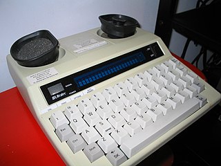
A telecommunications device for the deaf (TDD) is a teleprinter, an electronic device for text communication over a telephone line, that is designed for use by persons with hearing or speech difficulties. Other names for the device include teletypewriter (TTY), textphone, and minicom.
Telebit Corporation was a US-based modem manufacturer, known for their TrailBlazer series of high-speed modems. One of the first modems to routinely exceed 9600 bit/s speeds, the TrailBlazer used a proprietary modulation scheme that proved highly resilient to interference, earning the product an almost legendary reputation for reliability despite mediocre line quality. They were particularly common in Unix installations in the 1980s and 1990s.
Unstructured Supplementary Service Data (USSD), sometimes referred to as "quick codes" or "feature codes", is a communications protocol used by GSM cellular telephones to communicate with the mobile network operator's computers. USSD can be used for WAP browsing, prepaid callback service, mobile-money services, location-based content services, menu-based information services, and as part of configuring the phone on the network. The service does not require a messaging app, and does not incur charges.
Hayes Microcomputer Products was a U.S.-based manufacturer of modems. The company is known for the Smartmodem, which introduced a control language for operating the functions of the modem via the serial interface, in contrast to manual operation with front-panel switches. This smart modem approach dramatically simplified and automated operation. Today almost all modems use a variant of the Hayes command set.
GSM services are a standard collection of applications and features available over the Global System for Mobile Communications (GSM) to mobile phone subscribers all over the world. The GSM standards are defined by the 3GPP collaboration and implemented in hardware and software by equipment manufacturers and mobile phone operators. The common standard makes it possible to use the same phones with different companies' services, or even roam into different countries. GSM is the world's most dominant mobile phone standard.
The Microcom Networking Protocols, almost always shortened to MNP, is a family of error-correcting protocols commonly used on early high-speed modems. Originally developed for use on Microcom's own family of modems, the protocol was later openly licensed and used by most of the modem industry, notably the "big three", Telebit, USRobotics and Hayes. MNP was later supplanted by V.42bis, which was used almost universally starting with the first V.32bis modems in the early 1990s.
Novation, Inc., is an early modem manufacturer whose CAT series were popular in the early home computer market in the late 1970s and early 1980s, notably on the Apple II. The Hayes Smartmodem 300, introduced in 1981, helped kill off Novation and many other early modem companies over the next few years.
The Time Independent Escape Sequence, or TIES, is a modem protocol standard invented to avoid a patent held by Hayes Microcomputer Products. TIES is an escape sequence that switches the modem from "data mode" to "command mode", allowing instructions to be sent to the modem to control it while still connected to the remote modem.
Command mode and Data mode refers to the two modes in which a computer modem may operate. These modes are defined in the Hayes command set, which is the de facto standard for all modems. These modes exist because there is only one channel of communication between the modem and the computer, which must carry both the computer's commands to the modem, as well as the data that the modem is enlisted to transmit to the remote party over the telephone line.
NO CARRIER (capitalized) is a text message transmitted from a modem to its attached device, indicating the modem is not connected to a remote system.
A voice modem is an analog telephone data modem with a built-in capability of transmitting and receiving voice recordings over the phone line. Voice modems are used for telephony and answering machine applications. Similar to the Hayes command set used for data modems, in which the host PC commands the modem via a series of commands known as AT commands, there exists a well-defined set of common voice AT commands that are somewhat consistent throughout the industry.
A modulator-demodulator or modem is a computer hardware device that converts data from a digital format into a format suitable for an analog transmission medium such as telephone or radio. A modem transmits data by modulating one or more carrier wave signals to encode digital information, while the receiver demodulates the signal to recreate the original digital information. The goal is to produce a signal that can be transmitted easily and decoded reliably. Modems can be used with almost any means of transmitting analog signals, from light-emitting diodes to radio.
In mobile telephony GSM 03.38 or 3GPP 23.038 is a character encoding used in GSM networks for SMS, CB and USSD. The 3GPP TS 23.038 standard defines GSM 7-bit default alphabet which is mandatory for GSM handsets and network elements, but the character set is suitable only for English and a number of Western-European languages. Languages such as Chinese, Korean or Japanese must be transferred using the 16-bit UCS-2 character encoding. A limited number of languages, like Portuguese, Spanish, Turkish and a number of languages used in India written with a Brahmic scripts may use 7-bit encoding with national language shift table defined in 3GPP 23.038. For binary messages, 8-bit encoding is used.
GSM 03.40 or 3GPP TS 23.040 is a mobile telephony standard describing the format of the Transfer Protocol Data Units (TPDU) of the Short Message Transfer Protocol (SM-TP) used in the GSM networks to carry Short Messages. This format is used throughout the whole transfer of the message in the GSM mobile network. In contrast, application servers use different protocols, like Short Message Peer-to-Peer or Universal Computer Protocol, to exchange messages between them and the Short Message Service Center (SMSC).
This page is based on this Wikipedia article Text is available under the CC BY-SA 4.0 license; additional terms may apply. Images, videos and audio are available under their respective licenses.