Hydraulic motor

Last updated
Hydraulic gear motor Gear pump.png
Hydraulic gear motor
A small hydraulic motor Hydraulikmotor.jpg
A small hydraulic motor
Symbol: hydraulic motor Symbol Hydro motor.svg
Symbol: hydraulic motor

A hydraulic motor is a mechanical actuator that converts hydraulic pressure and flow into torque and angular displacement (rotation). The hydraulic motor is the rotary counterpart of the hydraulic cylinder as a linear actuator. Most broadly, the category of devices called hydraulic motors has sometimes included those that run on hydropower (namely, water engines and water motors) but in today's terminology the name usually refers more specifically to motors that use hydraulic fluid as part of closed hydraulic circuits in modern hydraulic machinery.

Contents

Conceptually, a hydraulic motor should be interchangeable with a hydraulic pump because it performs the opposite function – similar to the way a DC electric motor is theoretically interchangeable with a DC electrical generator. However, many hydraulic pumps cannot be used as hydraulic motors because they cannot be backdriven. Also, a hydraulic motor is usually designed for working pressure at both sides of the motor, whereas most hydraulic pumps rely on low pressure provided from the reservoir at the input side and would leak fluid when abused as a motor. [1]

History of hydraulic motors

Hydraulic machinery of Swing Bridge, River Tyne Machine Room. Swing Bridge - geograph.org.uk - 486049.jpg
Hydraulic machinery of Swing Bridge, River Tyne

One of the first rotary hydraulic motors to be developed was that constructed by William Armstrong for his Swing Bridge over the River Tyne. Two motors were provided, for reliability. Each one was a three-cylinder single-acting oscillating engine. Armstrong developed a wide range of hydraulic motors, linear and rotary, that were used for a wide range of industrial and civil engineering tasks, particularly for docks and moving bridges.

The first simple fixed-stroke hydraulic motors had the disadvantage that they used the same volume of water whatever the load and so were wasteful at part-power. [2] Unlike steam engines, as water is incompressible, they could not be throttled or their valve cut-off controlled. To overcome this, motors with variable stroke were developed. Adjusting the stroke, rather than controlling admission valves, now controlled the engine power and water consumption. One of the first of these was Arthur Rigg's patent engine of 1886. This used a double eccentric mechanism, as used on variable stroke power presses, to control the stroke length of a three cylinder radial engine. [2] Later, the swashplate engine with an adjustable swashplate angle would become a popular way to make variable stroke hydraulic motors.

Hydraulic motor types

Vane motors

Vane motor Rotary vane pump.svg
Vane motor

A vane motor consists of a housing with an eccentric bore, in which runs a rotor with vanes in it that slide in and out. The force differential created by the unbalanced force of the pressurized fluid on the vanes causes the rotor to spin in one direction. A critical element in vane motor design is how the vane tips are machined at the contact point between vane tip and motor housing. Several types of "lip" designs are used, and the main objective is to provide a tight seal between the inside of the motor housing and the vane, and at the same time to minimize wear and metal-to-metal contact.

Gear motors

Gear motor Gear pump.png
Gear motor

A gear motor (external gear) consists of two gears, the driven gear (attached to the output shaft by way of a key, etc.) and the idler gear. High pressure oil is ported into one side of the gears, where it flows around the periphery of the gears, between the gear tips and the wall housings in which it resides, to the outlet port. The gears mesh, not allowing the oil from the outlet side to flow back to the inlet side. For lubrication, the gear motor uses a small amount of oil from the pressurized side of the gears, bleeds this through the (typically) hydrodynamic bearings, and vents the same oil either to the low pressure side of the gears, or through a dedicated drain port on the motor housing, which is usually connected to a line that vents the motor's case pressure to the system's reservoir. An especially positive attribute of the gear motor is that catastrophic breakdown is less common than in most other types of hydraulic motors. This is because the gears gradually wear down the housing and/or main bushings, reducing the volumetric efficiency of the motor gradually until it is all but useless. This often happens long before wear causes the unit to seize or break down.

Gear motors can be supplied as single or double-directional based on their usage, and they are preferred in either aluminum or cast iron bodies, depending on application conditions. They offer design options that can handle radial loads. Additionally, alternative configurations include pressure relief valve, anti-cavitation valve, and speed sensor to meet specific application needs. [3]

Gerotor motors

Gerotor motor Gerotor anm.gif
Gerotor motor

The gerotor motor is in essence a rotor with N-1 teeth, rotating off center in a rotor/stator with N teeth. Pressurized fluid is guided into the assembly using a (usually) axially placed plate-type distributor valve. Several different designs exist, such as the Geroller (internal or external rollers) and Nichols motors. Typically, the Gerotor motors are low-to-medium speed and medium-to-high torque.

Axial plunger motors

For high quality rotating drive systems plunger motors are generally used. Whereas the speed of hydraulic pumps range from 1200 to 1800 rpm, the machinery to be driven by the motor often requires a much lower speed. This means that when an axial plunger motor (swept volume maximum 2 litres) is used, a gearbox is usually needed. For a continuously adjustable swept volume, axial piston motors are used.

Like piston (reciprocating) type pumps, the most common design of the piston type of motor is the axial. This type of motor is the most commonly used in hydraulic systems. These motors are, like their pump counterparts, available in both variable and fixed displacement designs. Typical usable (within acceptable efficiency) rotational speeds range from below 50 rpm to above 14000 rpm. Efficiencies and minimum/maximum rotational speeds are highly dependent on the design of the rotating group, and many different types are in use.

Radial piston motors

Staffa hydraulic motor Moteur hydraulique staffa.jpg
Staffa hydraulic motor
Calzoni hydraulic motor Moteur Hydraulique Calzoni.jpg
Calzoni hydraulic motor

Radial piston motors are available in two basic types: Pistons pushing inward, and pistons pushing outward.

Pistons pushing inward

The crankshaft type (e.g. Staffa or SAI hydraulic motors) with a single cam and the pistons pushing inwards is basically an old design but is one which has extremely high starting torque characteristics. They are available in displacements from 40 cc/rev up to about 50 litres/rev but can sometimes be limited in power output. Crankshaft type radial piston motors are capable of running at "creep" speeds and some can run seamlessly up to 1500 rpm whilst offering virtually constant output torque characteristics. This makes them still the most versatile design.

The single-cam-type radial piston motor exists in many different designs itself. Usually the difference lies in the way the fluid is distributed to the different pistons or cylinders, and also the design of the cylinders themselves. Some motors have pistons attached to the cam using rods (much like in an internal combustion engine), while others employ floating "shoes", and even spherical contact telescopic cylinders like the Parker Denison Calzoni type. Each design has its own set of pros and cons, such as freewheeling ability, high volumetric efficiency, high reliability and so on.

Pistons pushing outward

Multi-lobe cam ring types (e.g. Black Bruin, Rexroth, Hägglunds Drives, Poclain, Rotary Power or Eaton Hydre-MAC type) have a cam ring with multiple lobes and the piston rollers push outward against the cam ring. This produces a very smooth output with high starting torque but they are often limited in the upper speed range. This type of motor is available in a very wide range from about 1 litre/rev to 250 litres/rev. These motors are particularly good on low speed applications and can develop very high power.

Braking

Hydraulic motors usually have a drain connection for the internal leakage, which means that when the power unit is turned off the hydraulic motor in the drive system will move slowly if an external load is acting on it. Thus, for applications such as a crane or winch with suspended load, there is always a need for a brake or a locking device.

Uses

Hydraulic pumps, motors, and cylinders can be combined into hydraulic drive systems. One or more hydraulic pumps, coupled to one or more hydraulic motors, constitute a hydraulic transmission. [1]

Hydraulic motor and flow controller Hydraulic Motor and flow controller.jpg
Hydraulic motor and flow controller

Hydraulic motors are used for many applications now such as winches and crane drives, wheel motors for military vehicles, self-driven cranes, excavators, conveyor and feeder drives, cooling fan drives, mixer and agitator drives, roll mills, drum drives for digesters, trommels and kilns, shredders, drilling rigs, trench cutters, high-powered lawn trimmers, and plastic injection machines. Hydraulic motors are also used in heat transfer applications.

See also

Related Research Articles

<span class="mw-page-title-main">Pump</span> Device that imparts energy to the fluids by mechanical action

A pump is a device that moves fluids, or sometimes slurries, by mechanical action, typically converted from electrical energy into hydraulic energy.

<span class="mw-page-title-main">Starter (engine)</span> Device used to start an internal combustion engine

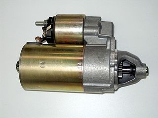
A starter is a device used to rotate (crank) an internal-combustion engine so as to initiate the engine's operation under its own power. Starters can be electric, pneumatic, or hydraulic. The starter can also be another internal-combustion engine in the case, for instance, of very large engines, or diesel engines in agricultural or excavation applications.

<span class="mw-page-title-main">Camshaft</span> Mechanical component that converts rotational motion to reciprocal motion

A camshaft is a shaft that contains a row of pointed cams, in order to convert rotational motion to reciprocating motion. Camshafts are used in piston engines, mechanically controlled ignition systems and early electric motor speed controllers.

<span class="mw-page-title-main">Air compressor</span> Machine to pressurize air

An air compressor is a machine that takes ambient air from the surroundings and discharges it at a higher pressure. It is an application of a gas compressor and a pneumatic device that converts mechanical power into potential energy stored in compressed air, which has many uses. A common application is to compress air into a storage tank, for immediate or later use. When the delivery pressure reaches its set upper limit, the compressor is shut off, or the excess air is released through an overpressure valve. The compressed air is stored in the tank until it is needed. The pressure energy provided by the compressed air can be used for a variety of applications such as pneumatic tools as it is released. When tank pressure reaches its lower limit, the air compressor turns on again and re-pressurizes the tank. A compressor is different from a pump because it works on a gas, while pumps work on a liquid.

<span class="mw-page-title-main">Fluid power</span> Use of fluids under pressure to generate, control, and transmit power

Fluid power is the use of fluids under pressure to generate, control, and transmit power. Fluid power is conventionally subdivided into hydraulics and pneumatics. Although steam is also a fluid, steam power is usually classified separately from fluid power. Compressed-air and water-pressure systems were once used to transmit power from a central source to industrial users over extended geographic areas; fluid power systems today are usually within a single building or mobile machine.

<span class="mw-page-title-main">Compressor</span> Machine to increase pressure of gas by reducing its volume

A compressor is a mechanical device that increases the pressure of a gas by reducing its volume. An air compressor is a specific type of gas compressor.

<span class="mw-page-title-main">Hydraulic machinery</span> Type of machine that uses liquid fluid power to perform work

Hydraulic machines use liquid fluid power to perform work. Heavy construction vehicles are a common example. In this type of machine, hydraulic fluid is pumped to various hydraulic motors and hydraulic cylinders throughout the machine and becomes pressurized according to the resistance present. The fluid is controlled directly or automatically by control valves and distributed through hoses, tubes, or pipes.

Power steering is a system for reducing a driver's effort to turn a steering wheel of a motor vehicle, by using a power source to assist steering.

<span class="mw-page-title-main">Pneumatic motor</span> Compressed air engine

A pneumatic motor, or compressed air engine, is a type of motor which does mechanical work by expanding compressed air. Pneumatic motors generally convert the compressed air energy to mechanical work through either linear or rotary motion. Linear motion can come from either a diaphragm or piston actuator, while rotary motion is supplied by either a vane type air motor, piston air motor, air turbine or gear type motor.

<span class="mw-page-title-main">Motor drive</span>

Motor drive means a system that includes a motor. An adjustable speed motor drive means a system that includes a motor that has multiple operating speeds. A variable speed motor drive is a system that includes a motor and is continuously variable in speed. If the motor is generating electrical energy rather than using it – this could be called a generator drive but is often still referred to as a motor drive.

<span class="mw-page-title-main">Hydristor</span>

Hydristor is a joining of the words 'hydraulic' and 'transistor'. The device invented by Tom Kasmer in 1996 and is based on the dual pressure balanced hydraulic vane pump invented by Harry F. Vickers in 1925.

<span class="mw-page-title-main">Axial engine</span>

An axial engine is a type of reciprocating engine with pistons arranged around an output shaft with their axes parallel to the shaft. Barrel refers to the cylindrical shape of the cylinder group whilst the Z-crank alludes to the shape of the crankshaft.

<span class="mw-page-title-main">Axial piston pump</span>

An axial piston pump is a positive displacement pump that has a number of pistons in a circular array within a cylinder block. It can be used as a stand-alone pump, a hydraulic motor or an automotive air conditioning compressor.

<span class="mw-page-title-main">Retarder (mechanical engineering)</span> Device for slowing down large vehicles

A retarder is a device used to augment or replace some of the functions of primary friction-based braking systems, usually on heavy vehicles. Retarders serve to slow vehicles, or maintain a steady speed while traveling down a hill, and help prevent the vehicle from "running away" by accelerating down the hill. They are not usually capable of bringing vehicles to a standstill, as their effectiveness diminishes as vehicle speed lowers. They are usually used as an additional "assistance" to slow vehicles, with the final braking done by a conventional friction braking system. As the friction brake will be used less, particularly at higher speeds, their service life is increased, and since in those vehicles the brakes are air-actuated helps to conserve air pressure too.

<span class="mw-page-title-main">Hydraulic pump</span> Mechanical power source

A hydraulic pump is a mechanical source of power that converts mechanical power into hydraulic energy. Hydraulic pumps are used in hydraulic drive systems and can be hydrostatic or hydrodynamic. They generate flow with enough power to overcome pressure induced by a load at the pump outlet. When a hydraulic pump operates, it creates a vacuum at the pump inlet, which forces liquid from the reservoir into the inlet line to the pump and by mechanical action delivers this liquid to the pump outlet and forces it into the hydraulic system. Hydrostatic pumps are positive displacement pumps while hydrodynamic pumps can be fixed displacement pumps, in which the displacement cannot be adjusted, or variable displacement pumps, which have a more complicated construction that allows the displacement to be adjusted. Hydrodynamic pumps are more frequent in day-to-day life. Hydrostatic pumps of various types all work on the principle of Pascal's law.

<span class="mw-page-title-main">Oil pump (internal combustion engine)</span> Internal combustion engine part that circulates engine oil under pressure

The oil pump is an internal combustion engine part that circulates engine oil under pressure to the rotating bearings, the sliding pistons and the camshaft of the engine. This lubricates the bearings, allows the use of higher-capacity fluid bearings and also assists in cooling the engine.

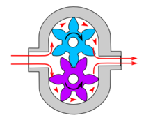
A rotodynamic pump is a kinetic machine in which energy is continuously imparted to the pumped fluid by means of a rotating impeller, propeller, or rotor, in contrast to a positive displacement pump in which a fluid is moved by trapping a fixed amount of fluid and forcing the trapped volume into the pump's discharge. Examples of rotodynamic pumps include adding kinetic energy to a fluid such as by using a centrifugal pump to increase fluid velocity or pressure.

PumpLinx is a 3-D computational fluid dynamics (CFD) software developed for the analysis of fluid pumps, motors, compressors, valves, propellers, hydraulic systems, and other fluid devices with rotating or sliding components.

<span class="mw-page-title-main">Rotary actuator</span>

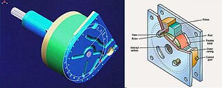
A rotary actuator is an actuator that produces a rotary motion or torque.

A cam engine is a reciprocating engine where, instead of the conventional crankshaft, the pistons deliver their force to a cam that is then caused to rotate. The output work of the engine is driven by this cam.

References

  1. 1 2 "Aeronautics - Aircraft Hydraulics - Level 3 (Hydraulic Motors)". Aeronautics Learning Laboratory for Science Technology and Research. 2004-03-12. Archived from the original on 2014-07-24. Retrieved 2014-01-27.
  2. 1 2 Pugh, B. (1980). The Hydraulic Age. Mechanical Engineering Publications. pp. 82–83. ISBN   0-85298-447-2.
  3. "Hydraulic Gear Motors as Design Configuration".{{cite web}}: CS1 maint: url-status (link)