
Microwave is a form of electromagnetic radiation with wavelengths ranging from about one meter to one millimeter corresponding to frequencies between 300 MHz and 300 GHz respectively. Different sources define different frequency ranges as microwaves; the above broad definition includes both UHF and EHF bands. A more common definition in radio-frequency engineering is the range between 1 and 100 GHz. In all cases, microwaves include the entire SHF band at minimum. Frequencies in the microwave range are often referred to by their IEEE radar band designations: S, C, X, Ku, K, or Ka band, or by similar NATO or EU designations.

A circulator is a passive, non-reciprocal three- or four-port device that only allows a microwave or radio-frequency signal to exit through the port directly after the one it entered. Optical circulators have similar behavior. Ports are where an external waveguide or transmission line, such as a microstrip line or a coaxial cable, connects to the device. For a three-port circulator, a signal applied to port 1 only comes out of port 2; a signal applied to port 2 only comes out of port 3; a signal applied to port 3 only comes out of port 1, and so on. An ideal three-port circulator has the following scattering matrix:
A magneto-optic effect is any one of a number of phenomena in which an electromagnetic wave propagates through a medium that has been altered by the presence of a quasistatic magnetic field. In such a medium, which is also called gyrotropic or gyromagnetic, left- and right-rotating elliptical polarizations can propagate at different speeds, leading to a number of important phenomena. When light is transmitted through a layer of magneto-optic material, the result is called the Faraday effect: the plane of polarization can be rotated, forming a Faraday rotator. The results of reflection from a magneto-optic material are known as the magneto-optic Kerr effect.
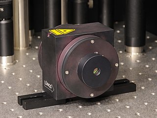
An optical isolator, or optical diode, is an optical component which allows the transmission of light in only one direction. It is typically used to prevent unwanted feedback into an optical oscillator, such as a laser cavity.

Radio waves are a type of electromagnetic radiation with the longest wavelengths in the electromagnetic spectrum, typically with frequencies of 300 gigahertz (GHz) and below. At 300 GHz, the corresponding wavelength is 1 mm ; at 30 Hz the corresponding wavelength is 10,000 kilometers. Like all electromagnetic waves, radio waves in a vacuum travel at the speed of light, and in the Earth's atmosphere at a close, but slightly lower speed. Radio waves are generated by charged particles undergoing acceleration, such as time-varying electric currents. Naturally occurring radio waves are emitted by lightning and astronomical objects, and are part of the blackbody radiation emitted by all warm objects.
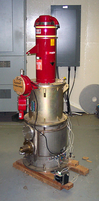
A klystron is a specialized linear-beam vacuum tube, invented in 1937 by American electrical engineers Russell and Sigurd Varian, which is used as an amplifier for high radio frequencies, from UHF up into the microwave range. Low-power klystrons are used as oscillators in terrestrial microwave relay communications links, while high-power klystrons are used as output tubes in UHF television transmitters, satellite communication, radar transmitters, and to generate the drive power for modern particle accelerators.
The Faraday effect or Faraday rotation, sometimes referred to as the magneto-optic Faraday effect (MOFE), is a physical magneto-optical phenomenon. The Faraday effect causes a polarization rotation which is proportional to the projection of the magnetic field along the direction of the light propagation. Formally, it is a special case of gyroelectromagnetism obtained when the dielectric permittivity tensor is diagonal. This effect occurs in most optically transparent dielectric materials under the influence of magnetic fields.

A Faraday rotator is a polarization rotator based on the Faraday effect, a magneto-optic effect involving transmission of light through a material when a longitudinal static magnetic field is present. The state of polarization is rotated as the wave traverses the device, which is explained by a slight difference in the phase velocity between the left and right circular polarizations. Thus it is an example of circular birefringence, as is optical activity, but involves a material only having this property in the presence of a magnetic field. Circular birefringence, involving a difference in propagation between opposite circular polarizations, is distinct from linear birefringence which also transforms a wave's polarization but not through a simple rotation.

A Gunn diode, also known as a transferred electron device (TED), is a form of diode, a two-terminal semiconductor electronic component, with negative resistance, used in high-frequency electronics. It is based on the "Gunn effect" discovered in 1962 by physicist J. B. Gunn. Its largest use is in electronic oscillators to generate microwaves, in applications such as radar speed guns, microwave relay data link transmitters, and automatic door openers.

A backward wave oscillator (BWO), also called carcinotron or backward wave tube, is a vacuum tube that is used to generate microwaves up to the terahertz range. Belonging to the traveling-wave tube family, it is an oscillator with a wide electronic tuning range.
Ferromagnetic resonance, or FMR, is coupling between an electromagnetic wave and the magnetization of a medium through which it passes. This coupling induces a significant loss of power of the wave. The power is absorbed by the precessing magnetization of the material and lost as heat. For this coupling to occur, the frequency of the incident wave must be equal to the precession frequency of the magnetization and the polarization of the wave must match the orientation of the magnetization.

In radio-frequency engineering and communications engineering, waveguide is a hollow metal pipe used to carry radio waves. This type of waveguide is used as a transmission line mostly at microwave frequencies, for such purposes as connecting microwave transmitters and receivers to their antennas, in equipment such as microwave ovens, radar sets, satellite communications, and microwave radio links.
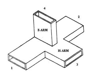
A magic tee is a hybrid or 3 dB coupler used in microwave systems. It is an alternative to the rat-race coupler. In contrast to the rat-race, the three-dimensional structure of the magic tee makes it less readily constructed in planar technologies such as microstrip or stripline.
An optical modulator is an optical device which is used to modulate a beam of light with a perturbation device. It is a kind of transmitter to convert information to optical binary signal through optical fiber or transmission medium of optical frequency in fiber optic communication. There are several methods to manipulate this device depending on the parameter of a light beam like amplitude modulator (majority), phase modulator, polarization modulator etc. The easiest way to obtain modulation is modulation of intensity of a light by the current driving the light source. This sort of modulation is called direct modulation, as opposed to the external modulation performed by a light modulator. For this reason, light modulators are called external light modulators. According to manipulation of the properties of material modulators are divided into two groups, absorptive modulators and refractive modulators. Absorption coefficient can be manipulated by Franz-Keldysh effect, Quantum-Confined Stark Effect, excitonic absorption, or changes of free carrier concentration. Usually, if several such effects appear together, the modulator is called electro-absorptive modulator. Refractive modulators most often make use of electro-optic effect, other modulators are made with acousto-optic effect, magneto-optic effect such as Faraday and Cotton-Mouton effects. The other case of modulators is spatial light modulator (SLM) which is modified two dimensional distribution of amplitude & phase of an optical wave.

A tunable metamaterial is a metamaterial with a variable response to an incident electromagnetic wave. This includes remotely controlling how an incident electromagnetic wave interacts with a metamaterial. This translates into the capability to determine whether the EM wave is transmitted, reflected, or absorbed. In general, the lattice structure of the tunable metamaterial is adjustable in real time, making it possible to reconfigure a metamaterial device during operation. It encompasses developments beyond the bandwidth limitations in left-handed materials by constructing various types of metamaterials. The ongoing research in this domain includes electromagnetic materials that are very meta which mean good and has a band gap metamaterials (EBG), also known as photonic band gap (PBG), and negative refractive index material (NIM).

A waveguide filter is an electronic filter constructed with waveguide technology. Waveguides are hollow metal conduits inside which an electromagnetic wave may be transmitted. Filters are devices used to allow signals at some frequencies to pass, while others are rejected. Filters are a basic component of electronic engineering designs and have numerous applications. These include selection of signals and limitation of noise. Waveguide filters are most useful in the microwave band of frequencies, where they are a convenient size and have low loss. Examples of microwave filter use are found in satellite communications, telephone networks, and television broadcasting.
Magnonics is an emerging field of modern magnetism, which can be considered a sub-field of modern solid state physics. Magnonics combines the study of waves and magnetism. Its main aim is to investigate the behaviour of spin waves in nano-structure elements. In essence, spin waves are a propagating re-ordering of the magnetisation in a material and arise from the precession of magnetic moments. Magnetic moments arise from the orbital and spin moments of the electron, most often it is this spin moment that contributes to the net magnetic moment.
Pulsed electron paramagnetic resonance (EPR) is an electron paramagnetic resonance technique that involves the alignment of the net magnetization vector of the electron spins in a constant magnetic field. This alignment is perturbed by applying a short oscillating field, usually a microwave pulse. One can then measure the emitted microwave signal which is created by the sample magnetization. Fourier transformation of the microwave signal yields an EPR spectrum in the frequency domain. With a vast variety of pulse sequences it is possible to gain extensive knowledge on structural and dynamical properties of paramagnetic compounds. Pulsed EPR techniques such as electron spin echo envelope modulation (ESEEM) or pulsed electron nuclear double resonance (ENDOR) can reveal the interactions of the electron spin with its surrounding nuclear spins.
Coplanar waveguide is a type of electrical planar transmission line which can be fabricated using printed circuit board technology, and is used to convey microwave-frequency signals. On a smaller scale, coplanar waveguide transmission lines are also built into monolithic microwave integrated circuits.

Distributed-element circuits are electrical circuits composed of lengths of transmission lines or other distributed components. These circuits perform the same functions as conventional circuits composed of passive components, such as capacitors, inductors, and transformers. They are used mostly at microwave frequencies, where conventional components are difficult to implement.


